



Contents: Removal 🠛 Installation 🠛
It is recommended to remove the power unit downwards together with the subframe, after which, if necessary, the subframe and gearbox can be disconnected.
Removal
- place the car on a ramp or lift;
- disconnect the wires from the battery and remove it;
- remove the front wheels and mudguards;
- remove the protective cover of the power unit;
- drain the coolant by disconnecting the drain hose from the radiator;
- drain the oil from the gearbox;
- if you plan to disassemble the engine, drain the engine oil and remove the oil filter;
- remove the decorative grille of the radiator grille;
- remove the front bumper;
- loosen the brake caliper mounting bolts and remove them along with the ABS sensors from the steering knuckles without disconnecting the brake hoses. Tie the calipers to body parts or suspension springs without putting any load on the brake hoses;
- disconnect the shock absorber struts from the steering knuckles by unscrewing the nuts and removing the bolts;
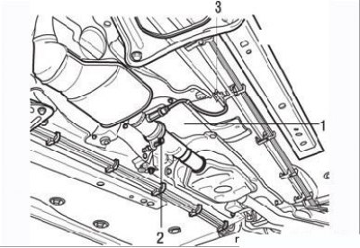
Figure 3.1. Removing the heat shield (1), the clamp (2) connecting the catalytic converter and the front muffler, disconnecting the connector (3) of the oxygen concentration sensor in the exhaust gases
- under the car, unscrew the bolts and remove the exhaust system heat shield (Figure 3.1);
- unscrew and remove the clamp connecting the catalytic converter and the front muffler;
- disconnect the exhaust gas oxygen sensor connectors;
- disconnect the gear shift drive rod from the gearbox (or selector cable for automatic transmission);
- disconnect the "mass" tires from the gearbox;
- disconnect the catalytic converter mounting parts from the exhaust manifold and move it away from the intermediate section of the exhaust pipe;
- disconnect the exhaust pipe from the engine;
- remove the air intake duct from the air filter;
- unscrew the expansion tank mounting bolts and move the tank to the side. If necessary, disconnect the hoses from the thermostat housing;
- disconnect the brake booster vacuum hose from the intake manifold;
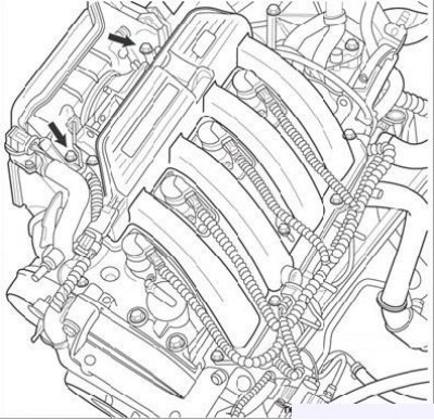
Figure 3.2. Air filter housing mounting bolts
- remove the air filter housing by unscrewing the mounting bolts (Figure 3.2);
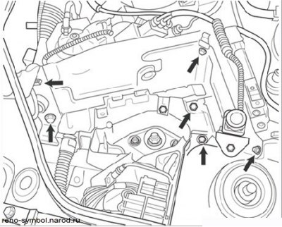
Figure 3.3. Fastening elements (arrows) of the ECU and the fuel supply switch bracket during a vehicle impact
- remove the bracket of the electronic control unit (ECU), having first disconnected the contact connector and the bracket of the inertia switch to stop the fuel supply when the vehicle is hit (Figure 3.3);
- disconnect the vacuum hose from the brake booster;
[This note was copied from the resource: RENAULTBOOK.ru]
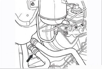
Figure 3.4. Fastening the heater hoses (arrows) to the engine shield
- disconnect the heater hoses from the engine shield (Figure 3.4), remembering their position, and move them to the side. The hoses can have two types of quick-release fittings: with an outer ring, which must be turned to the left to remove, or with plastic protrusions that must be squeezed and removed by pressing the fastener in the direction of the engine shield;
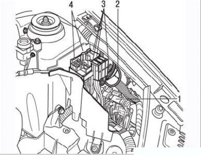
Figure 3.5. Removing the relay block (1), wiring block (2), fuse holders (3) and block with fuse holders (4) from the engine
- disconnect the relay block, wiring harness, fuse box from the engine and remove the fuse boxes from it (Figure 3.5);
- disconnect the wiring block from the adsorber and the adsorber hose from the intake manifold;
- disconnect the fuel pedal cable from the throttle body;
- disconnect the clutch cable if a manual transmission is installed;
- on a vehicle with an automatic transmission, disconnect the selector lever cable;
- remove the power steering fluid reservoir from the bracket and place it on the engine;
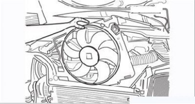
Figure 3.6. Removing the electric fan unit from the radiator
- remove the upper radiator supports from the engine bay crossmember and tie the radiator to the engine to prevent damage. If necessary, remove the electric fan assembly from the rear of the radiator (Figure 3.6). Please note that the lower radiator supports are mounted on a subframe that is removed together with the radiator;
- disconnect the pipes from the fuel rail and plug their openings;
- on models with air conditioning, remove the compressor from the engine without disconnecting the lines and secure the compressor away from the work area;
- remove the air conditioner condenser and secure it to the side without disconnecting the pipes from it;
- set the front wheels to the straight-ahead position, bend back the protective rubber cuff on the bottom of the steering column, unscrew the nut and remove the eccentric bolt securing the steering shaft cardan joint fork;
Caution: To prevent the airbag from deploying, be sure to lock the steering wheel in the straight-ahead position before disconnecting the steering shaft from the steering gear.
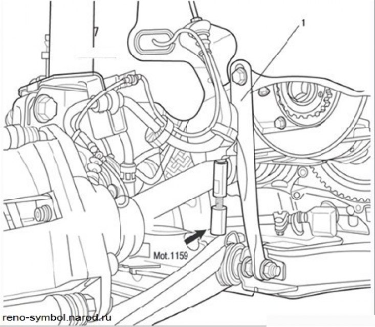
Figure 3.7. Installing tool Mot. 1159 between the subframe and the cylinder block:
1 – coupler
- install the Mot. 1159 tool on the right side of the engine between the subframe and the cylinder block (Figure 3.7). If there is no device, wedge the power unit and subframe using wooden blocks, unscrew the tie fastener and remove it;
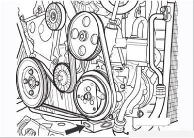
Figure 3.8. Installing the gasket between the multi-functional bracket and the subframe
- install a wooden spacer between the multi-function bracket and the subframe (Figure 3.8);
- insert a wooden spacer between the gearbox and the subframe;
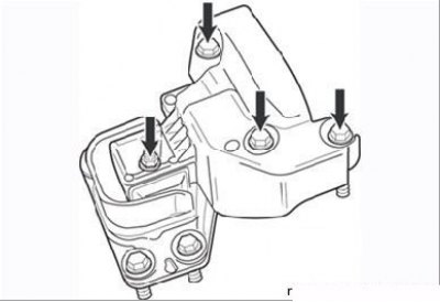
Figure 3.9. Removing the upper casing of the engine pendulum support
- remove the upper cover of the engine pendulum mount (Figure 3.9);
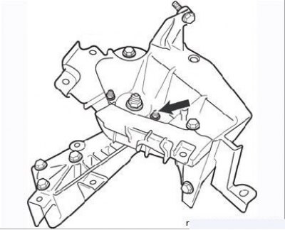
Figure 3.10. Loosening the nut (arrow) on the engine pendulum mount
- remove the nut on the engine pendulum mount, then use a bronze drift to knock out the support mounting stud (Figure 3.10);
- support the engine with a hoist;
- remove the left engine mount;
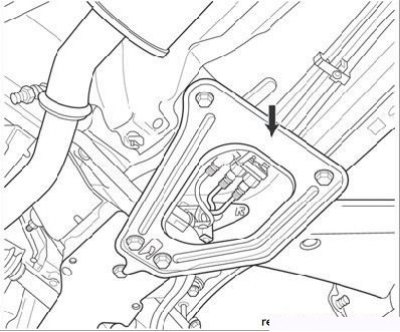
Figure 3.11. Removing the subframe reinforcement (arrow)
- disconnect the subframe reinforcements and remove them (Figure 3.11);
- loosen the bolts securing the subframe to the body by one or two turns. Do not unscrew them completely;
- lower the front of the car so that the subframe with the power unit can be placed on wooden blocks;
- unscrew the subframe mounting bolts. Together with an assistant, carefully lift the front of the car, making sure that the engine-related parts, assemblies and wiring are disconnected from it;
- if possible, move the vehicle back to free up working space;
- lift the engine with a hoist to remove the bolts securing it to the subframe. Disconnect the front wheel drive shafts from the gearbox and remove the power unit from under the car;
- if it is necessary to disconnect the engine and gearbox, remember the location of the wires connected to the power unit.
Note: Before carrying out work that requires disconnecting the engine, gearbox and subframe, mark the position of tool Mot. 1159 on the subframe.
Installation
The power unit is installed in the reverse order of removal.
To facilitate alignment of the subframe to the body, install two threaded rods into the front mounting holes of the subframe. Tighten the front subframe mounting bolts to 62 N·m, the rear ones to 105 N·m.
Install the heat shields correctly. Apply Loctite Frenblok to the threads of the front brake caliper mounting bolts and tighten them to the specified torque. Press the brake pedal several times to set the wheel cylinder pistons to the operating position.
Please do the following:
- filling the engine and gearbox with oil (if necessary);
- filling the cooling system and removing air from it.
Powertrain mounts
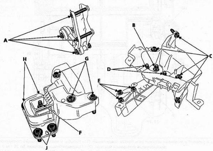
Tightening torques for the powertrain support bolts. A = 62 Nm, B = 62 Nm, C = 21 Nm, D = 21 Nm, E = 62 Nm, F = 44 Nm, G = 62 Nm, H = 62 Nm, J = 62 Nm.