
- turn the crankshaft pulley bolt clockwise with a wrench or head so that the pistons are approximately in the middle of their stroke to prevent valve failure;
- lay a new gasket on the cylinder block;
- if the lower part of the intake manifold was removed, it must be installed at this stage before tightening the mounting bolts, making sure that the side facing the valve timing mechanism is installed flush with the side of the cylinder head;
- carefully lower the head onto the cylinder block without displacing the gasket;
- insert checked (or replaced) bolts and tighten them by hand;
- tighten the cylinder head bolts to 20 Nm in the order shown in Figure 3.21, then tighten all the bolts in the same order by 240°±6°. After this procedure, no further tightening of the bolts is required. In the absence of a goniometric nozzle on the crank, pre-apply with paint an angular marking on the cylinder head;
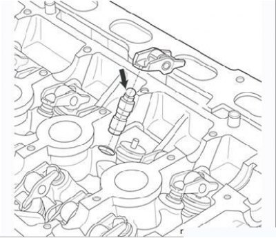
Figure 3.22. Checking the hydraulic pusher (force is applied in the direction of the arrow)
- check hydraulic pushers (Figure 3.22), by pressing your finger on their end in the direction of the arrow indicated in the figure. If the plunger sinks, then the hydraulic pusher needs to be pumped. To do this, completely immerse the hydraulic pusher in a container with engine oil and press its end several times;
- remove the hydraulic pushers from the cells of the oil box and install each in its place;
- one by one, remove the roller rocker arms from the boxes and put them in their places;
- lubricate the camshaft bearings. Do not allow oil to get on the mating surface of the cylinder head cover;
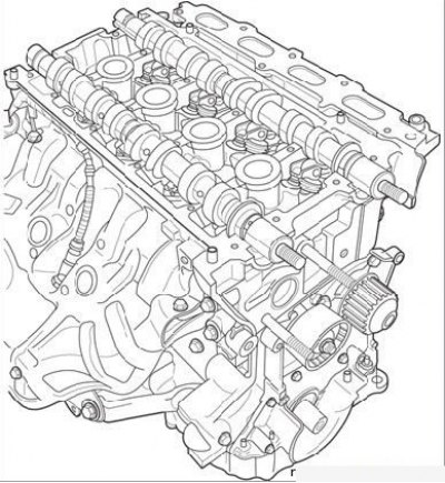
Figure 3.23. Installation of camshafts (toothed sprockets removed)
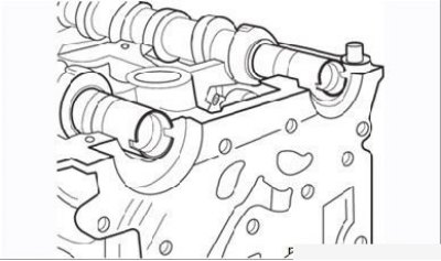
Figure 3.24. The location of the grooves on the ends of the camshafts (flywheel side view)
- put the camshafts on the marked marks in their places (Figure 3.23). Grooves at the ends of the shafts (flywheel side) must be horizontal (Figure 3.24);
- set the piston of the first cylinder to the TDC of the compression stroke, as described below in the subsection «Toothed belt»;
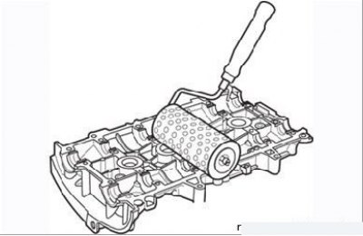
Figure 3.25. Roller application of sealant to the surface of the cylinder head cover
- make sure the mating surfaces of the head and cover are clean. They must be clean, dry and free of grease (especially avoid touching them with your fingers, so as not to leave traces of fat). Using a roller, apply Loctite 518 to the surface of the cylinder head cover until it turns reddish (Figure 3.25);
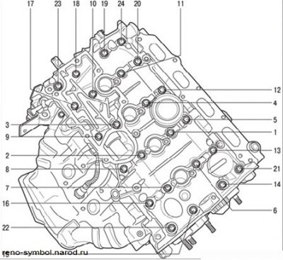
Figure 3.26. Cylinder head cover bolt tightening sequence
- install the cylinder head cover and tighten the bolts of its fastening in the sequence shown in Figure 3.26. The tightening torques are given in table. 3.1;
Table 3.1 Torques and tightening sequence for cylinder head cover bolts

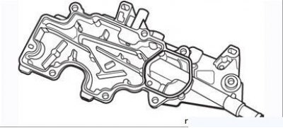
Figure 3.27. The mating surface of the oil separator, on which the sealant is applied
- make sure the mating surfaces of the oil separator and cylinder head are clean. They must be clean, dry and free of grease (especially avoid touching them with your fingers, so as not to leave traces of fat). Apply Loctite 518 to the surface of the oil separator with a roller until it turns reddish (Figure 3.27);
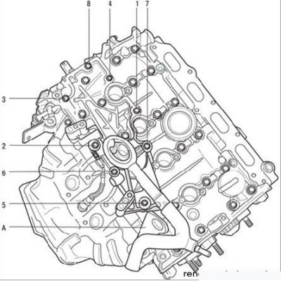
Figure 3.28. The sequence of tightening the oil separator mounting bolts: A - lifting eye
- install the oil separator, tightening its fastening bolts to the specified torque, and the lifting eye (Figure 3.28);
- perform the remaining operations in the reverse order of removal;
- fill the engine with oil and coolant, start the engine, make sure it runs normally and there are no oil and fluid leaks.