



Install the cylinder head.
Tighten the cylinder head bolts.
Refill the hydraulic lifters, as the hydraulic fluid may leak from the lifters if they are not used for a long time.
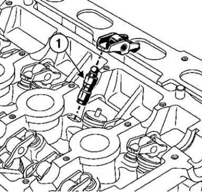
Fig. 2.186. Installing the pusher: 1 – pusher
To check for refilling, press the top of the plunger with your thumb (fig. 2.186).
If the pusher plunger is recessed:
- immerse the pushers in a container with diesel fuel;
- then install the pushers.
Install:
- rocker arms;
- camshafts, lubricating the bearing journals with engine oil.
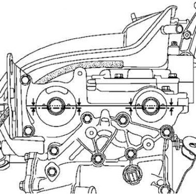
Fig. 2.187. Installing camshafts
Turn the camshafts so that the grooves on their ends are horizontal and below the shaft axes (fig. 2.187).
Caution! Do not allow oil to come into contact with the mating surfaces of the cylinder head cover.
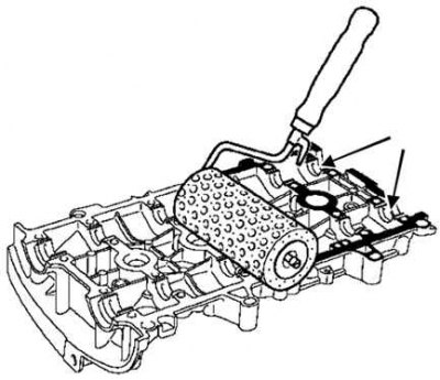
Fig. 2.188. Applying the composition with a roller to the mating surface of the cylinder head cover
Apply LOCTITE 518 to the cylinder head cover mating surface with a paint roller until it turns a reddish color (fig. 2.188).
Use a cloth to remove any LOCTITE 518 that has come into contact with the camshaft bearing supports in the cylinder head cover.
Remove the cylinder head cover.
Tightening procedure
Tighten in the order shown to the specified torque:
- mounting bolts 22, 23, 20, 13 of the cylinder head cover (80 Nm);
- bolts 1–12, 14–19, 21–24 for fastening the cylinder head cover (120 Nm).
Loosen bolts 22, 23, 20, 13 in the order shown.
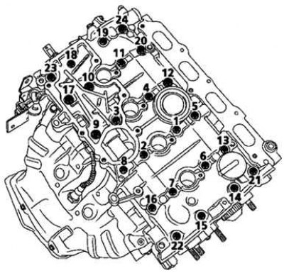
Fig. 2.189. Tightening order of the cylinder head and cylinder block cover bolts
Tighten in the specified order to the required torque the cylinder head cover mounting bolts 22, 23, 20, 13 (120 Nm) (fig. 2.189).
Install the oil separator.
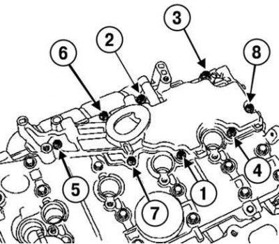
Fig. 2.190. Tightening order of oil separator mounting bolts
[Original article is on the portal: www.renaultbook.ru]
Tighten in the order shown in Figure 2.190 to the required torque:
- new oil separator mounting bolts (in unthreaded holes) (15 Nm);
- oil separator mounting bolts (new or old) in holes with pre-cut threads (10 Nm).
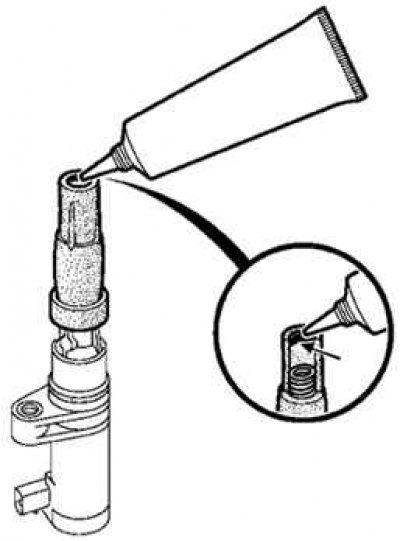
Fig. 2.191. Places of application of grease on the inner circumference of the high-voltage wire cap
Apply 2mm diameter strips of GRAISSE FLUOREE grease to all four ignition coils around the inside circumference of the high tension cable boot (fig. 2.191).
Tighten the spark plugs.
tighten the spark plugs to the specified torque (25–30 Nm) using the spark plug wrench set (Ele. 1382).
Install the ignition coils.
Tighten to the specified torque:
- ignition coil mounting bolts (in threaded holes) (12 Nm);
- ignition coil mounting bolts (in unthreaded holes) (15 N·m).
Be sure to replace all intake manifold gaskets.
Tighten the intake manifold mounting bolts to the specified torque (9 Nm).
Install:
- throttle body;
- air filter housing.