
You will need: keys «on 10», «at 12», «at 17», spark plug wrench, magnetized screwdriver (or tweezers) for removing crackers of valve springs, a device for compressing valve springs.
1. Remove all spark plugs (see «Replacement and maintenance of spark plugs»).
2. Turn away three nuts of fastening and remove a thermoscreen of a final collector.
3. Turn away other nuts of fastening of a final collector and remove a collector and the laying installed under it (see «Exhaust manifold gasket replacement»).
4. Remove the four upper bolts securing the inlet pipe to the block head, unscrew the three lower nuts and remove the inlet pipe together with the throttle assembly and the fuel rail (see «Replacing the intake pipe seal»). Remove the intake pipe seals.
Note. Replace the inlet pipe seals with new ones each time the joint is disassembled.
5. Turn out three bolts of fastening and remove the thermostat (see «Removal and installation of the thermostat»).
6. Remove the valve rocker shaft complete with rocker arms and camshaft (see «Camshaft Replacement»).
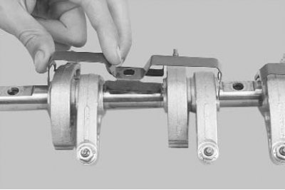
7. If necessary, remove the rocker clamps from the axle...
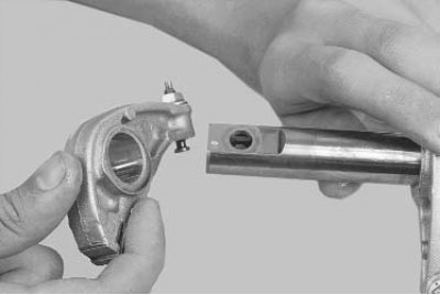
8.... and rocker arms.
Note. If you do not intend to replace the rocker arms, their axle and camshaft, do not remove the rocker arms from the axle in order to install them in their original places during assembly.
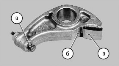
9. Examine rocker arms of valves. Replace the rocker arm if there is severe, clearly visible wear on the surface in contact with the camshaft cam. Check the cleanliness of hole b for supplying lubricant to the camshaft cam. Check the condition of the head of the adjusting bolt a and if it shows obvious signs of wear...
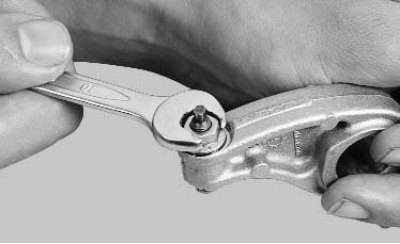
10.... unscrew the locknut of the bolt...
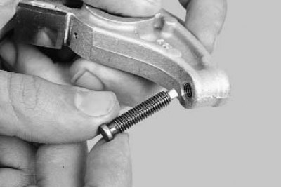
11.... and remove the bolt from the rocker arm.
12. Install a tool for compressing valve springs, compress the springs, remove crackers, spring plates, springs (see «Replacement of valve stem seals») and remove the valves from the guide bushings.
Attention! After prolonged use, a mushroom-shaped burr may form on the upper end of the valve. Before removing the valve from the guide sleeve, remove this burr with a file. It is strictly forbidden to knock out the valve from the guide sleeve with a hammer through the mandrel without removing the burr, as this will inevitably damage the inner surface of the sleeve.
13. Remove tar deposits from the top surface of the head and from the inlet ports. These deposits can be softened and washed away with kerosene or diesel fuel.
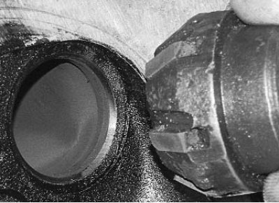
14. Clean the combustion chambers and exhaust channels from carbon deposits. Remove carbon deposits with a round metal brush mounted in an electric drill chuck.
Note. Pre-soak the soot with kerosene. Be careful not to inhale the dust generated when cleaning the combustion chambers. To prevent the formation of dust, periodically moisten the soot with kerosene.
15. Clean the inside surfaces of the valve guides with a thin cylindrical copper wire brush clamped in an electric drill chuck.
16. Remove the burnt remnants of the sealing gasket from the surface of the head to the cylinder block.
Attention! It is forbidden to clean the mating surface of the head with metal brushes or emery cloth. Use a hardwood or plastic spatula after softening the rest of the gasket with solvent.
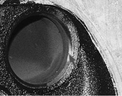
17. After cleaning, inspect the head of the block to prevent its operation with damage to the threaded holes, cracks (especially between valve seats and in exhaust passages), corrosion, inclusions of foreign materials, shells and fistulas.
Attention! It is forbidden to brew cracks, sinks and fistulas. Replace defective head.
18. Using a metal ruler mounted on the edge and a feeler gauge, check the flatness of the surface of the head to the block in the longitudinal and transverse directions, as well as diagonally. If the gap between the edge of the ruler and the surface of the head is greater than 0.05 mm, replace the head.
19. Clean the surfaces of the flanges of the head for installing the intake pipe and exhaust manifold from the remnants of gaskets and deposits.
20. Check up presence of deformation of flanges for an inlet pipe and a final collector, replace the deformed head.
21. Damaged threaded holes repair by threading with taps or by installing a repair sleeve (screw-in).
22. Determine the wear of the valve guide bushings by measuring the inner diameter of the bushing hole and the diameter of the valve stem, and by the difference of these dimensions, determining the gap. The maximum permissible gap for wear for intake valves is 0.10 mm, for exhaust valves - 0.15 mm.
23. If the backlash remains more than maximum admissible and at installation of new valves, replace directing plugs. Have the guide bushings replaced by a specialist workshop that has the proper tools and equipment.
24. Check the condition of the valve seats. Seat faces must be free of wear, pitting, corrosion, and other defects. The valve seats can be replaced by a specialist workshop. Minor damage (minor scratches, scratches, etc.) can be removed by lapping valves (see «Lapping of valves»).
25. More significant defects in valve seats are eliminated by grinding. Saddles must be ground in a specialized workshop, as this requires special tools and equipment. If significant defects in the seats cannot be corrected by grinding, replace the seats.
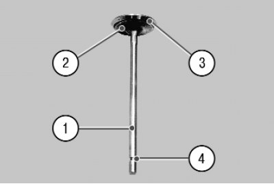
26. Remove carbon from the valves and inspect them. Deformation of the valve stem 1 and cracks on its plate 2 are not allowed. Replace valve if damaged. Check whether the working face is too worn or damaged. 3. Grinding of the working face of the valves is allowed (in repair shops with appropriate equipment). After grinding, the thickness of the cylindrical part of the plate must be at least 0.5 mm for intake valves and at least 1.0 mm for exhaust valves. Minor scratches and scratches on the chamfer can be removed by lapping the valve against the seat (see «Lapping of valves»).
Attention! To avoid scratches on the valve stems, do not clean them with wire brushes or metal scrapers.
27. Check the concentricity of the valve disc and seat: apply a thin layer of paint to the chamfer of the valve head (e.g. Prussian blue), insert it into the guide sleeve and, pressing it lightly against the seat, turn it. The traces of paint on the bevel of the seat indicate the concentricity of the valve and seat.
28. Check the condition of the grooves 4 (see photo p. 26) valve stem for crackers. If there are traces of chipping of the edges of the grooves and wear of the cylindrical part, replace the valve.
29. Replace valve stem seals regardless of their condition.
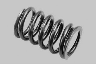
30. Inspect the valve springs. Cracks and reduction of elasticity of springs are not allowed. Springs can be installed in one of two types. Nominal length of the spring of the first type in a free state (46,5±2) mm, the second type - (46,64±2) mm. The length with fully compressed coils is 26.0 and 23.63 mm, respectively. Springs, the length of which in the free state is less than the permissible, bent (deviation of the spring axis from the vertical in the free state is more than 4°) and replace with cracks.
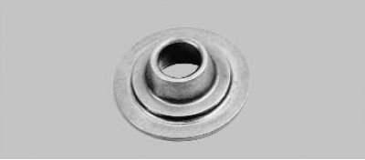
31. Check up a condition of plates of springs. Replace plates with significant wear of the support grooves for the springs.
32. Establish all removed details and knots of a head of the block of cylinders in sequence, return to removal.
33. Always replace the gaskets of the cylinder head, intake pipe and exhaust manifold with new ones, since gaskets removed from the engine, even outwardly undamaged gaskets, may be heavily compressed and will not ensure tightness of the seal.