



You can replace the oil seals without removing the cylinder head from the engine.
You will need: all the tools needed to remove the cylinder head cover (see "Replacing the cylinder head cover gasket"), as well as a 12 mm wrench, tweezers (or a magnetized screwdriver) for extracting crackers from valve spring plates...
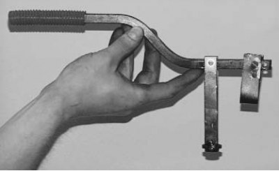
...a device for compressing valve springs.
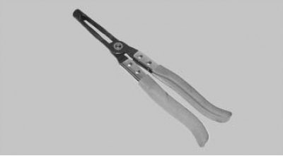
...tick-borne...
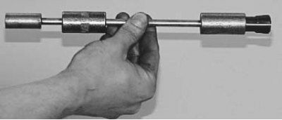
...or an inertial valve stem seal puller. The puller shown has a mandrel on the other end for pressing the caps on. If you don't have such a puller, you'll need pliers to remove the caps and a mandrel of the appropriate diameter to press them onto the valve guides.
1. Disconnect the wire from the negative terminal of the battery.
2. Remove all spark plugs (see "Replacement and maintenance of spark plugs").
3. Remove the cylinder head cover (see "Replacing the cylinder head cover gasket").
4. Set the piston of the 1st cylinder to the TDC position of the compression stroke (see "Setting the piston of the first cylinder to the TDC position of the compression stroke").
Note. With this position of the crankshaft, the pistons of the 1st and 4th cylinders are at TDC. This makes it possible to "de-clamp" the valves of these cylinders without the risk of dropping them into the cylinder.
Note: To set the piston of the 1st cylinder to the TDC position of the compression stroke, it is necessary to remove the upper cover of the timing belt (to gain access to the timing marks on the camshaft pulley and on the cylinder head), which entails labor-intensive preliminary operations to remove the right support of the power unit suspension. With an accuracy sufficient for setting the pistons of the 1st and 4th cylinders to the TDC position when replacing the oil scraper caps, the camshaft can be set to the required position, checking it visually. When turning the crankshaft, the camshaft must be installed so that the heels of the rocker arms of the drive of both valves of the 1st or 4th cylinders rest on the back of the cams of the camshaft, and the rocker arms can be moved by "rocking" within the gap.
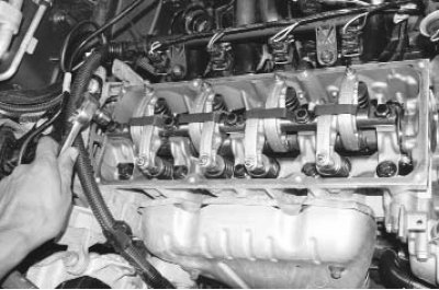
5. Evenly loosen the five bolts securing the valve drive rocker arm shaft...
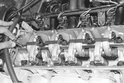
6. ... remove the bolts from the cylinder head and axle holes...
Note: Please note that the bolts have different head shapes. Install the bolts in their original locations when reassembling.
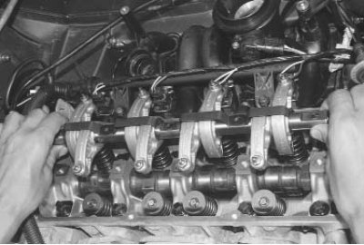
7. ...and remove the axle assembly with the rocker arms.
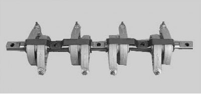
Note: If you do not plan to replace the valve rocker arms, their shaft and camshaft, do not remove the rocker arms from the shaft so that they can be installed in their original places during assembly.
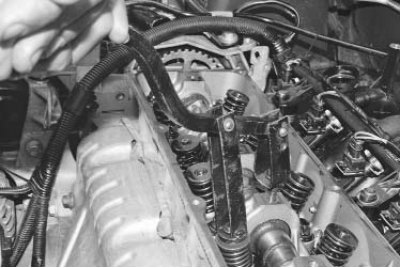
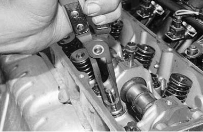
8. Install the valve spring compressor by screwing the valve rocker shaft mounting bolt into one of the cylinder head holes and hooking the compressor onto this bolt.
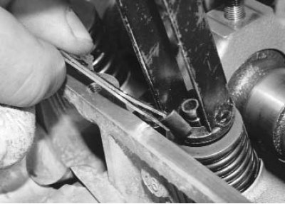
9. Compress the valve spring with the device and remove two crackers from the spring plate using tweezers or a magnetized screwdriver. Then remove the device.
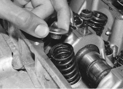
10. Remove the spring plate...
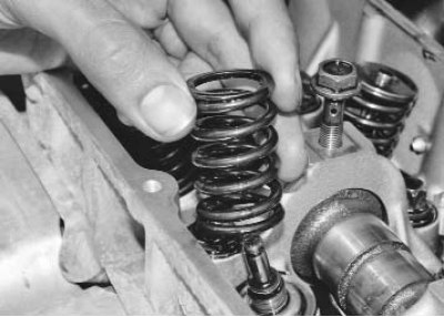
11. ...and the valve spring.
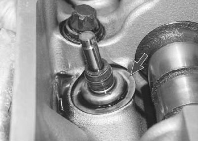
Note: The valve spring support washer does not need to be removed as it does not interfere with replacing the valve stem seal.
12. Press the valve stem seal off the valve guide bushing. To do this, install the collet of the inertial valve stem seal puller on the seal and sharply hit the collet bushing with the striker. Then, just as sharply hit the handle of the tool with the striker, thereby pressing the seal off the bushing.
13. If there is no inertial cap puller, remove the cap with a special pliers-type puller or pliers, applying force strictly upwards and without turning the cap, so as not to damage the valve guide sleeve.
Warning! Do not remove the cap by prying it from both sides with screwdrivers. The guide bushing on which the cap is placed is made of metal ceramics, and its edge easily breaks off.

14. Before installing new valve stem seals, we recommend removing the springs from them, otherwise the caps can be damaged when they pass through the grooves for the crackers on the valves. If the new caps come with a plastic installation sleeve, you can leave the springs on. In this case, put the sleeve on the valve stem.
15. Lubricate the inner surface of the valve stem seal with engine oil and slide the seal along the valve stem to the guide sleeve.
16. Install the mandrel for pressing the cap. Press the cap in with light blows of the striker on the mandrel until it stops. If you do not have a special device, you can select a cylindrical mandrel of a suitable diameter and press the cap through it with light blows of a hammer on the mandrel.
Note: You can use the long head from the tool kit as a mandrel. Choose a head with 12 faces and a chamfer inside the hole so that the head contacts the cap in a continuous circle.
17. Remove the guide sleeve from the valve stem or place the spring on the cap if it was removed.
18. Install the spring and valve plate in the reverse order of removal. Install the crackers using the device so that they fit into the grooves of the valve stem. After installing the crackers, hit the end of the valve with a hammer through a metal rod so that the crackers fit into place.
Warning! If the cam followers are installed at an angle and remain unsecured, the "unsecured" valve will fall into the cylinder when the engine is started, which will lead to serious engine failure.
19. Similarly, replace the oil seals of the second valve of the 1st cylinder and two valves of the 4th cylinder.
20. Turn the crankshaft half a turn so that the pistons of the 2nd and 3rd cylinders are at TDC, and replace the oil seals of the remaining valves.
21. After installing the valve rocker shaft assembly with the rocker arms on the engine, check and, if necessary, adjust the clearances in the valve drive (see "Adjusting valve clearances").
Note: Tighten the rocker arm axle mounting bolts evenly to a torque of 23 N·m (2.3 kgf·m).
22. Install all removed parts in the reverse order of removal.