



- the pressure in the engine lubrication system has dropped. The cause of this malfunction is often increased wear of the camshaft journals and camshaft bearing seats in the cylinder head. If the seats are worn out, the cylinder head is replaced as an assembly, since the seats are made directly in its body;
- valve knocking that cannot be eliminated by adjusting the clearances in the valve drive mechanism. May occur due to increased wear of the camshaft cams due to the use of low-quality engine oil or damage to the oil filter.
Note: If the camshaft cams are heavily worn, replacing the camshaft often requires replacing the valve rocker arms as well.
Due to the specific layout of the Renault Logan engine compartment, it is not possible to remove the camshaft directly on the car. To do this, you need to remove the cylinder head.
You will need: the same tools as for removing the cylinder head (see "Cylinder Head Gasket Replacement") and replacement of oil scraper caps, except for those that are directly necessary for their replacement (tools are used only for preparatory operations) (cm. "Replacing valve stem seals"), as well as additional keys "11", "16" (socket head), "at 25", TORX T30, micrometer.
1. Remove the cylinder head (see "Cylinder Head Gasket Replacement").
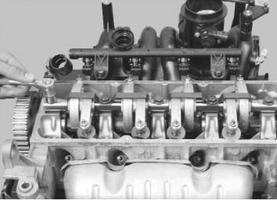
2. Evenly loosen the tightening and unscrew the five bolts securing the valve rocker arm shaft...
Note: Please note that the bolts have different head shapes. Install the bolts in their original locations when reassembling.
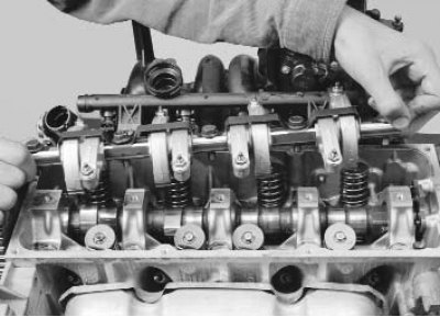
3. ...and remove the axle assembly with the rocker arms.
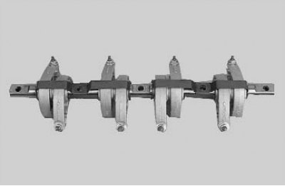
Note: If you do not plan to replace the valve rocker arms and their shaft, do not remove the rocker arms from the shaft so that they can be installed in their original positions during assembly.
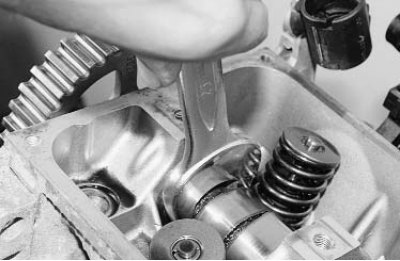
4. Hold the camshaft from turning with a hex key...
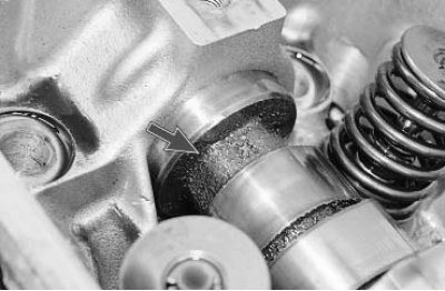
Note: The retaining hex is cast into the front journal of the camshaft bearing.
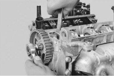
5. ...unscrew the camshaft toothed pulley mounting bolt...
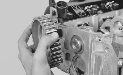
6. ...and remove the pulley.
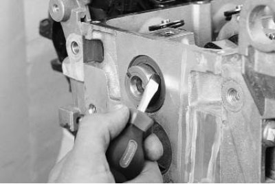
7. Using a screwdriver, pry...
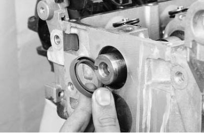
8. ... remove the camshaft oil seal from its socket in the cylinder head.
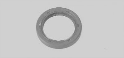
Note: Replace the camshaft oil seal with a new one each time it is removed.
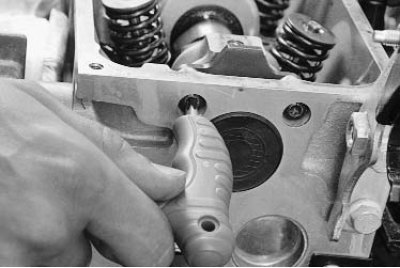
9. At the rear end of the cylinder head, unscrew the two screws securing the camshaft thrust flange...
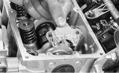
10. ...and remove the flange.
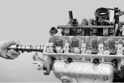
11. Carefully, trying not to damage the working surfaces of the bearings with the sharp edges of the cams, remove the camshaft from the cylinder head beds.
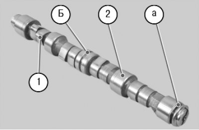
12. Inspect the camshaft. The surfaces of bearing journals 2 and cams 1 must be well polished and without damage, and groove a for the thrust flange must not show signs of excessive wear or nicks. No scoring, nicks, scratches, or aluminum drag from the bearing seats in the cylinder head are allowed on the working surfaces of journals 2. If the working surfaces of cams 1 show signs of seizure, overheating, deep scratches, or faceted wear, or uniform wear exceeding 0.5 mm, replace the shaft. Carefully clean channel b for oil supply in the middle bearing journal from deposits.
Attention! Grinding the camshaft cams to eliminate step wear is prohibited, since changing the cam profile dimensions will disrupt the valve timing.
13. In workshops equipped with special tools and devices, you can check the radial runout of the camshaft journals. If its value is more than 0.02 mm or the journals are not aligned, replace the shaft, since its straightening is not allowed.
Attention! When installing a new camshaft, we recommend replacing the valve rocker arms with new ones. Before the first start of the engine and to improve the running-in conditions, we recommend adding an anti-seize anti-friction additive to the engine oil.
14. After installing the camshaft, check its axial clearance. If it is more than 0.15 mm, replace the thrust flange.
15. Install the camshaft into the cylinder head and all removed parts in the reverse order of removal.
16. Install the cylinder head onto the engine (see "Cylinder Head Gasket Replacement").