
English Русский
Български
Беларускі
Український
Српски
Hrvatski
Română
Polski
Slovenský
Magyar
Bookmark Contacts Articles Sitemap
Company vehicles Peugeot Company vehicles Opel Company vehicles Skoda Company vehicles Land Rover Company vehicles Mitsubishi Company vehicles Volkswagen Company vehicles Honda
RenaultBook.ru


Duster   Fluence   Kangoo   Laguna   Logan   Megane   Sandero   Scenic   Symbol   Clio   Other
Renault 19 (1988-1996) Espace I and II (1984-1996) Espace III (1996-2002)

Oil Pump (and Pan) — Removal and Installation (Renault Espace I)

  • Main
  • Renault
  • Espace I and II (1984-1996)
  • Power unit
  • Engine repair
  • Oil Pump (and Pan) — Removal and Installation
0
Contents: 4-cylinder engines 🠛 V6 Engine 🠛

4-cylinder engines


1. This section describes the process of removing the oil pump from a vehicle engine. The instructions apply to both gasoline and diesel engines. Some differences exist if the crankcase is equipped with a thrust plate.

2. The front of the vehicle must be securely supported on axle stands.

3. First, drain the engine oil and remove the oil pan. Remove the mudguard underneath the car. Loosen the four bolts at the rear of the engine and remove the clutch housing bulkhead. Remove the bolts in a circular pattern.

4. Remove the frame crossbar bolts. To remove the bolts, use the 11 mm extended socket head (wrench).

5. Remove the engine mount nuts from the underside of the vehicle and lift the engine with a winch until the oil pan is accessible. If the oil pan is made of aluminum, mark the location of each bolt as the bolts are not all the same length. Clean the cylinder block of any remaining gasket.

6. If the installation is correct, unscrew the drive cover bolts (see illustration).
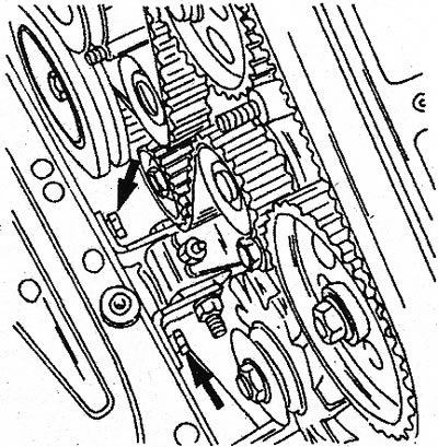
22.6 The arrows show the location of the engine thrust plate attachment (turbodiesel engine)

22.6 The arrows show the location of the engine thrust plate attachment (turbodiesel engine)


7. If the thrust plate is not installed, remove the oil pump from the bottom of the crankcase. On a turbocharged diesel engine, the oil pump may be installed with the oil distribution pipe shown (see illustration). In this case, unscrew the union nuts and remove the pump together with the shaft. Now the pump can be removed from the shaft.
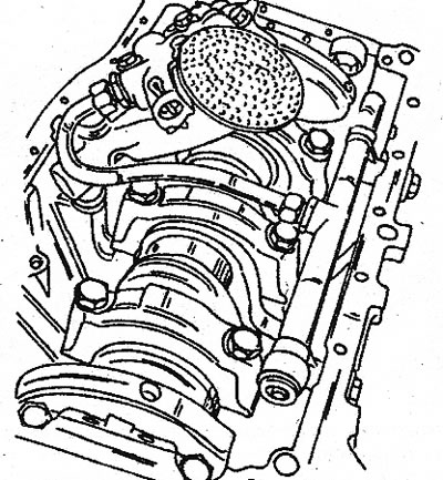
22.7 Position of the oil pump together with the oil distribution pipe (if installed)

22.7 Position of the oil pump together with the oil distribution pipe (if installed)


8. If a thrust plate is installed, perform the above described work before removing the oil pan from the cylinder block. The oil pump is located in the location shown (see illustration). Remove the four bolts (1) of the oil receiver screen and remove the pump cover. Remove the rotors from the pump housing. Remove the two remaining bolts and pull out the oil pump. Thoroughly clean the surface of the oil pan and crankcase.
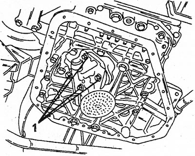
22.8 Four bolts (1) securing the oil pump cover to the crankshaft housing. After removing the…

22.8 Four bolts (1) securing the oil pump cover to the crankshaft housing. After removing the cover, the oil pump rotors are exposed


9. Installation of the oil pump and oil pan is as follows:

10. The oil pump drive shaft has a retaining ring at the pump inlet. Push the shaft into the pump so that it fits into the retaining ring (see illustration). If a thrust plate is installed, install the oil pump and tighten both screws. Lubricate the rotors well and insert them into the pump channel.
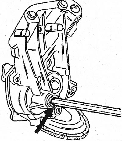
22.10 The arrow indicates where the retaining ring is located in the drive shaft of the 4-cylinder…

22.10 The arrow indicates where the retaining ring is located in the drive shaft of the 4-cylinder engine pump


12. Install the pump cover with the receiver screen and tighten the four bolts (see illustration 22.8).

13. Install the oil pan with a new sealing gasket and tighten the bolts in a circular sequence to a tightening torque of 10 Nm. In an aluminum oil pan, screw the bolts in according to their marks. Do not apply sealant to the gasket surface.

14. On a turbocharged diesel engine, install the oil distribution pipe and connect it to the pump.

15. Install the engine on the brackets, install the drive cover on the engine (if there is) and fill the engine with the prescribed amount of oil. Filling volumes of diesel engines depend on the year of manufacture and are indicated in the specifications. Fill only with oil intended for this engine.


V6 Engine


16. Drain the engine oil.

17. Remove in the order shown: the alternator belt tensioner and the power steering pump, as well as other components: the air filter, the cylinder head cover and the shield at the front of the vehicle.

18. Engage the gear and apply the parking brake.

19. Place the front of the vehicle on axle stands and remove the drive belt pulley nut from below. Press the pulley out with a special tool.

20. Disengage the gear and turn the crankshaft so that the woodruff key is on top of the shaft, as marked with the number "1" (see illustration).
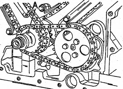
22.20 Before removing the oil pump from the V6 engine, the Woodruff key (1) must be positioned at…

22.20 Before removing the oil pump from the V6 engine, the Woodruff key (1) must be positioned at the top. The pulley must already be removed


21. Carefully press the pulley.

22. Remove the camshaft drive cover together with the sealing gasket. The gasket should always be replaced.

23. Unscrew the three bolts of the oil pump sprocket and remove the sprocket together with the chain.

24. Remove the pump cover (see illustration) and the pump from the cylinder block. Do not hit the part indicated by the arrow with a mallet.
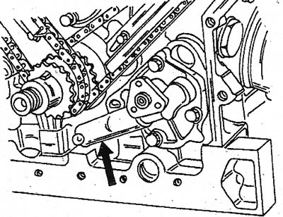
20.24 View of the V6 engine oil pump. Never strike the part indicated by the arrow with a mallet

20.24 View of the V6 engine oil pump. Never strike the part indicated by the arrow with a mallet


25. Remove the slave rotor from the pump housing. Remove the safety valve cotter pin and remove the bushing, spring, plunger and piston from the bore. Clean all parts thoroughly. If there are obvious signs of wear, replace the pump.
This article is available on: russian, bulgarian, belarusian, ukrainian, serbian, croatian, romanian, polish, slovak, hungarian
Article has been reviewed by editor: Fedoseev Denis
Share with friends:
Previous
Espace I and II: Engine repair
Next

Camshaft Seals — Replacement
Toothed Drive Belt — Replacement
Camshaft — Removal from an Installed Engine
Crankshaft seals — replacement
Flywheel (drive pulley) — removal and installation
Oil pump — overhaul
Oil filter
Checking engine oil pressure
Crankcase thrust plate (4-cylinder engine)
Oil pan
Other articles on other Renault models

➽ Oil pump — removal and installation Renault Duster 1 (2009-2017)
➽ Removal the water pump inlet pipe Renault Fluence 1 (2009-2020, petrol)
➽ Oil pump Renault Kangoo 1 (1997-2007)
➽ Checking fuel pump performance (all engines) Renault Laguna 2 (2001-2007)
➽ Replacing the chain and gear of the oil pump drive Renault Logan 1 (2004-2012, petrol)
Link to this article in different formats
Reviews and comments of visitors
No comments yet


Add two numbers 18 + 34


Renault 19 (1988-1996) 
  • General information
  • Maintenance
  • Power unit
  • Engine repair
  • Exhaust system
  • Cooling system
  • Supply system
  • Single-point injection
  • Multi-point injection
  • Diesel injection system
  • Transmission
  • Clutch
  • Car gearbox
  • Chassis, running gear
  • Car suspension
  • Steering
  • Brake system
  • Wheels and tires
  • Body and interior
  • Exterior (external elements)
  • Interior (internal elements)
  • Heating and ventilation
  • Electrical equipment
  • Equipment and devices
  • Headlights and lighting
  • Ignition system
  • Power devices
  • Electrical circuits
Espace I and II (1984-1996) 
  • General information
  • Introduction to the guide
  • Troubleshooting
  • Power unit
  • Engine repair
  • Cooling system
  • Carburetor fuel system
  • Injection fuel system
  • Diesel fuel system
  • Ignition system
  • Transmission
  • Clutch
  • Car gearbox
  • Drive shafts
  • Chassis, running gear
  • Brake system
  • Steering
  • Front suspension
  • Rear suspension
  • Body and interior
  • Exterior (external elements)
  • Interior (internal elements)
  • Doors, locks and windows
  • Electrical equipment
  • Equipment and devices
  • Electrical circuits
Espace III (1996-2002) 
  • General information
  • Introduction to the manual
  • User manual
  • Power unit
  • Petrol engines F3R
  • Petrol engines Z7X
  • Diesel engines G8T
  • Diesel engines G9T
  • Transmission
  • Clutch
  • Mechanical gearbox
  • Automatic gearbox
  • Drive shafts
  • Chassis, running gear
  • Steering
  • Front suspension
  • Rear suspension
  • Brake system
  • Body and interior
  • Exterior (external elements)
  • Interior (internal elements)
  • Doors, locks and windows
  • Heating and ventilation
  • Electrical equipment
  • Equipment and instruments
  • Power devices
  • Electrical circuits
RenaultBook.ru © 2018–2026 | Mobile version | News and articles | Sitemap: EN BG BY UA RS HR RO PL SK HU | Administration | Site search | Bookmark
Duster 1 (2009-2017) | Fluence 1 (2009-2020, petrol) | Kangoo 1 (1997-2007) | Laguna 2 (2001-2007) | Logan 1 (2004-2012, petrol) | Logan 2 (2012-2020) | Megane 1 (1995-2002) | Megan 2 (2002-2009, petrol) | Sandero 1 (2007-2012, petrol) | Scenic 1 (1996-2003) | Symbol 1 (1999-2008, petrol) | Symbol 2 (2008-2013, petrol) | Renault 19 (1988-1996) | Espace I and II (1984-1996) | Espace III (1996-2002) | Clio 1 (1990-1998) |
We want your visit to be comfortable 😌 and use cookies 🍪 to do so.