
2. After removing the pump cover, the bottom surface looks like shown (see illustration). Loosen the bolts (1) And (2). Please note that the bolts of different engines are not the same and have different tightening torques, i.e. either mark the bolts accordingly, or follow illustration 26.3 when installing the plate.
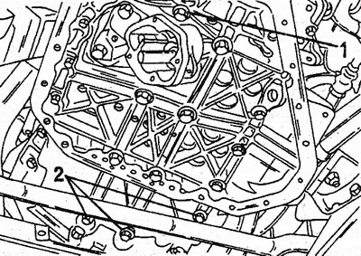
26.2 Bolts (1) And (2) fasten the thrust plate to the bottom surface of the crankcase. bolts (2) come out with the plate
3. Three bolts marked (2) are removed together with the thrust plate. Remove the seal. Thoroughly clean the oil pan and cylinder block surface, and install a new gasket lubricated with a small amount of sealant on the bottom surface of the crankcase. Now install the thrust plate (including oil pump, pump rotors and oil pump cover) (see illustration).
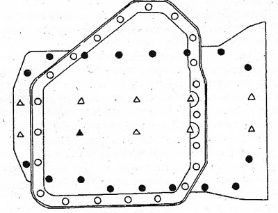
26.3 Bolt positions of the four different types of fastening of the thrust plate to the underside of the crankcase. Dimensions and tightening torques will be indicated below
4. Insert only suitable bolts and tighten them to the specified torque:
A) Bolts marked with black dots (17 pieces, M7) tighten with a torque of 12-18 Nm.
b) Bolts marked with circles (21 pieces, M6) tighten with a torque of 7-11 Nm.
With) Bolt marked with a black triangle (1 piece, M10) tighten with a torque of 32-48 Nm.
d) Bolts marked with white triangles (9 pieces, M10) tighten with a torque of 32-48 Nm.