
4-cylinder petrol engines
1. The toothed drive belt must be changed every 100,000 km, even if it is still in good condition. Follow the instructions exactly when replacing the belt. If the installation of the camshaft relative to the crankshaft is violated, the valves can knock on the pistons.
2. Disconnect the battery and shield under the engine.
3. Remove the water pump and power steering drive belt.
4. Remove the cylinder head cover and remove the spark plugs.
5. Put the ring wrench on the crankshaft timing belt pulley bolt and set the piston of the first cylinder to TDC.
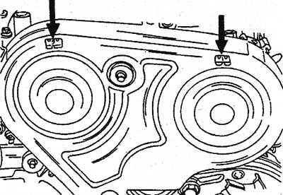
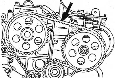
6. The crankshaft should now be precisely held in this position. First, check from the flywheel side whether the mark for setting the ignition timing on the flywheel is opposite «0» - markings on the clutch housing, and the alignment mark on the camshaft sprocket opposite the tongue in the camshaft drive cover or look in the lower window of the camshaft drive cover (see illustration). Secondly, check if both rocker arms of the first cylinder have clearance if they are moved. Now the crankshaft must not be turned until the toothed drive belt is installed.
20.6 Sight glasses in the camshaft cover of some engines. Top for camshaft sprocket, bottom for crankshaft sprocket
7. Partially drain the coolant and close the drain hose on the manifold.
8. Remove the drive toothed belt cover.
9. Loosen the toothed drive belt tensioner. To do this, loosen both nuts, press the roller and tighten both nuts again.
10. Carefully remove the toothed drive belt. Make sure that the belt does not get oil or grease and do not bend it. The direction of movement of the belt must be marked with chalk or paint on the back of the belt.
11. If necessary, remove the camshaft pulley. When doing so, mark the groove for the key, as this is necessary for installation.
12. Pay attention to the following instructions:
13. The camshaft sprocket has two keyways. When installing the pulley, the marked groove must align with the key. Tighten the bolt with a torque of 50 Nm.
14. Camshaft sprocket has two marks (see illustration). Label on one side (7), opposite is a small ledge (6). They are used in conjunction with a keyway (5) on J6R and J7R engines. The installation mark is on the opposite side (1) and two ledges (2) in relation to a rectangular hole (4). These alignment marks, together with the keyway (3) used on J7T engines. Which version of the sprocket uses a toothed drive belt with square teeth.
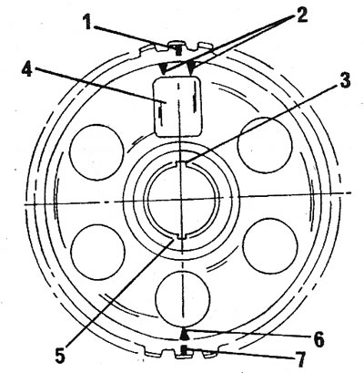
20.14 Camshaft sprocket
15. On newer models, a toothed drive belt with rounded teeth is installed, i.e. parts for the old toothed drive belt will not fit the new one. In addition, both belts have a different number of teeth. The following description assumes that the engine has been completely disassembled. If the belt is removed as described above, you can proceed to additional work.
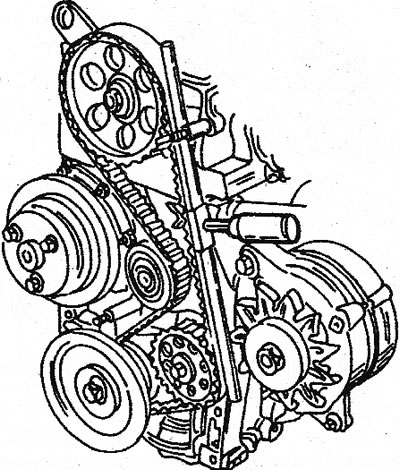
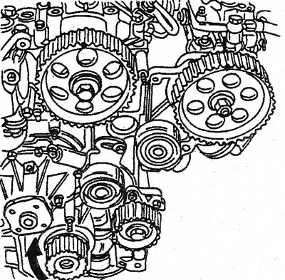
16. Assemble the engine as described in chapter 3, before installing the cylinder head. Install the cylinder head for now. Align the three pulleys as shown (see illustration).
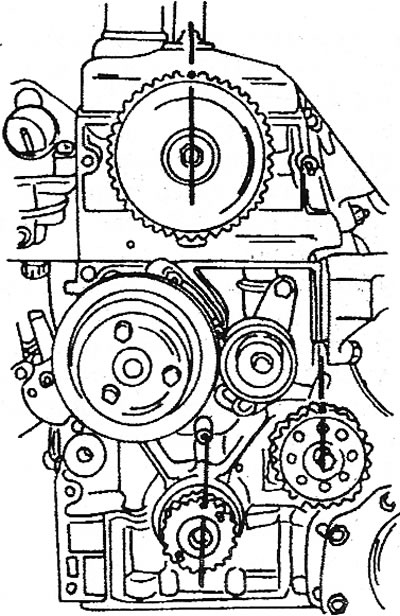
20.16 Pulley alignment. Position before installing toothed drive belt
17. Turn the crankshaft until the ignition timing mark on the flywheel is aligned with the mark «0» on the clutch housing. Also, after installing the camshaft drive cover, you can check through the viewing window whether the installation mark on the crankshaft sprocket is visible (see illustration 20.6).
18. Rotate the intermediate shaft until the pulley alignment mark is in line with the rib in the cylinder block.
19. Temporarily put the sprocket on the camshaft (with marked keyway) and rotate the camshaft so that the alignment mark on the pulley is in line with the vertical line passing through the axis of the rocker arms.
20. After all the pulleys and sprockets are adjusted, inspect everything again (see illustration 20.16).
21. Now install the cylinder head as described when assembling the engine. Tighten the toothed drive belt as follows:
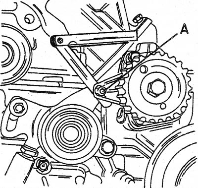
22. Referring to illustration 20.16, check again that the alignment marks of the three sprockets are aligned and put on the toothed drive belt. Segments «A» and «IN» after installation should not be loosened (see illustration).
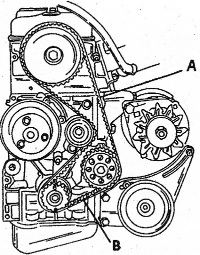
20.22 Parts «A» and «IN» must not sag before tensioning the toothed drive belt
23. Loosen both idler roller bolts a quarter of a turn. At the same time, the tension roller is set to a new position and tensions the toothed drive belt. Tighten both screws after adjusting the tension roller.
24. Rotate the crankshaft two full revolutions of the engine in its normal direction.
25. Check the tension of the toothed drive belt using a special tool (see illustration). The toothed drive belt must have a certain amount of deflection, which depends on the shape of the belt teeth:
- A) The deflection of the square tooth drive belt is 5.5-7.0mm.
- b) For a belt with rounded teeth, this value is 6.0-8.0 mm.
20.25 Special tool for tensioning the toothed drive belt, mounted on a long section
26. If you do not have a special tool, the mentioned deviation can be checked by pressing on the toothed drive belt. Adjust by loosening and tightening both tensioner screws.
27. Reinstall all removed parts and let the engine run for 10-15 minutes.
Turbocharged diesel engine
28. The toothed drive belt must be changed every 90,000-100,000 km, even if it may still work. To fix the crankshaft exactly at TDC, you need a special locking pin (№861). The locking pin diameter is 8 mm, i.e. a punch of the same diameter will fit it.
29. Remove the shield under the engine and disconnect the battery.
30. Remove all parts that block access to the front of the engine.
31. Remove glow plugs. As a result, it is easier to crank the engine when installed at TDC.
32. Put the key on the crankshaft bolt and turn the engine until the piston of the first cylinder is at TDC. To accurately determine the dead center, view the alignment marks of the camshaft sprocket and fuel pump drive gear through the viewing windows (see illustration). If the camshaft drive cover is removed, temporarily install it again.
20.32 If the piston of the first cylinder is at TDC, both timing marks must be visible through «windows»
33. In this position of the engine, install the locking pin at a certain point (see illustration). The pin goes into a hole in the crankshaft, however, be careful not to get it into one of the locating holes in the rotating parts. Once the pin is installed, the crankshaft can no longer move. The mounting holes are 12mm in diameter, and since the pin hole is 8mm, it is easy to tell if the pin is in the wrong hole. Remove the camshaft cover again. The cylinder head cover can also be removed.
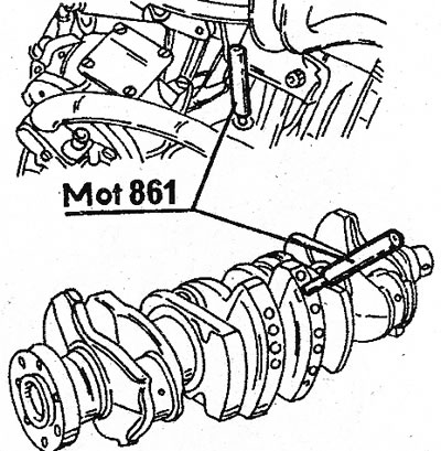
20.33 The crankshaft locking pin is installed in the indicated location in the cylinder block. Mounting holes are also visible
34. Loosen both belt tensioner nuts (see illustration). Pull back the timing belt tensioner plunger and tighten again.
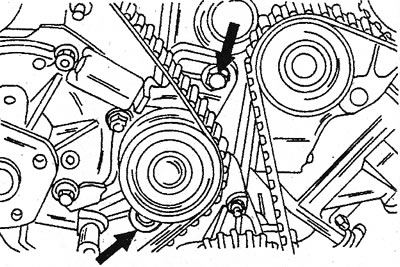
20.34 Timing belt tensioner bolts
35. If the removed drive belt is to be installed again, mark the direction of travel on the back of the belt. If the belt gets oil or grease, it must be replaced.
36. When installing a toothed drive belt, follow the instructions exactly.
37. Assemble the engine as described in chapter 3 before installing the cylinder head. Install the cylinder head for now. Align the three stars as shown (see illustration).
20.37 Correct installation of the camshaft sprocket, fuel pump drive gear (upstairs) and crankshaft sprockets
38. Turn the crankshaft until the piston of the first cylinder is at TDC and (see illustration 20.33) insert the locking pins into the cylinder block and crankshaft (it is naturally pushed in if only the belt is changed). Move the crankshaft back and forth. If it does not move, the pin has been installed correctly. The crankshaft sprocket alignment mark is in the position shown in illustration 20.37 (bottom arrow).
39. Turn the camshaft sprocket until the mark in the camshaft sprocket is aligned with the protrusion in the camshaft drive cover.
40. Turn the fuel pump drive gear until the mark is in line with the fuel pump fin.
41. After all gear sprockets turn, check everything again (see illustration 20.37).
42. Install the cylinder head as described when assembling the engine. Now put on the drive belt as follows:
43. Referring to illustration 20.37, make sure once again that the alignment marks of the three sprockets are aligned and install the drive belt. Temporarily install the camshaft cover and make sure both timing marks are visible (see illustration 20.32). Put on the belt as described below.
44. If the engine has been completely disassembled, measure the gap between the intermediate shaft housing and the belt tensioner. Insert a measuring probe 0.10 mm thick (see illustration).
20.44 Measure the clearance between the intermediate shaft housing and the belt tensioner. Turn bolt to adjust tension (A)
45. Loosen locknut and bolt. Then tighten the locknut again and remove the dipstick. Install the drive belt carefully. Make sure that all the teeth are in the slots of the crankshaft, camshaft and fuel pump sprocket.
46. As a further check, count the number of tooth bases between both upper alignment marks. If there are 20 of them, you can be sure that the belt is installed correctly.
47. Loosen both nuts no more than a quarter of a turn (see illustration 20.34). At the same time, set the tensioner to a new position and tension the drive belt. Tighten both nuts to the new tensioner position.
Drive belt tension
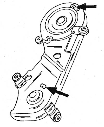
48. Perform the following work with particular care. Tension is set using special tools (see illustration 20.25), installed in places shown by arrows (see illustration):
20.48 Drive belt tension is measured at the location indicated by the arrow
49. Rotate the crankshaft two full turns in the normal direction of engine rotation.
50. The tension of the drive belt is determined using a special tool (see illustration 20.25), with the only difference that it is installed between both sprockets (see illustration 20.48). Attach the device to the belt. The belt should bend 3-5 mm. If necessary, loosen the tensioner screws again and adjust the tension. If you do not have a special tool, press the drive belt with your finger.
51. Reinstall all removed parts and let the engine run for 10-15 minutes.
V6 engine
52. The removal of parts belonging to the gas distribution mechanism was described during engine disassembly. When installing chain sprockets, camshaft drive chains, etc. see chapter for description engine assembly.