
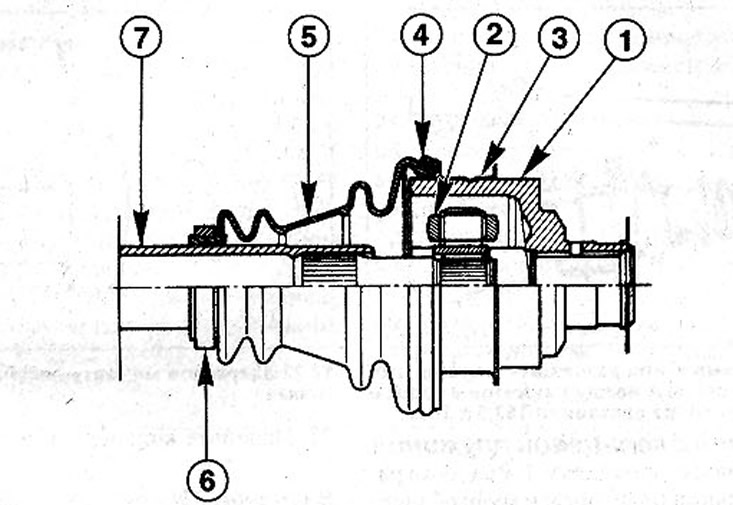
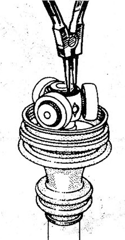
12.0 Right inner CV joint without ball bearing
1 - clutch; 2 - cross; 3 - metal cuff; 4 - annular spring; 5 - rubber cuff; 6 - rubber ring; 7 - shaft
Inner CV joint of the right shaft with a collar without a ball bearing (see illustration 12.0)
Removing
1. Remove the drive shaft.
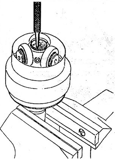
2. Option with a metal cuff. Bend the cuff with pliers at three points (see illustration).
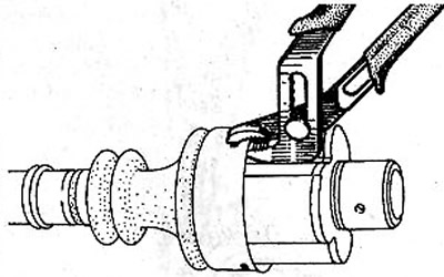
12.2 Bend the cuff with pliers at three points
3. Remove the rubber Cuff and knock the metal off the shaft with a punch.
Ring spring version
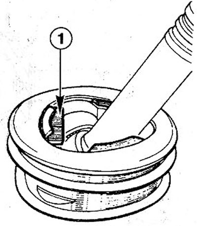
4. Remove the annular spring 1 from the cuff on the coupling 2 of the CV joint (see illustration).
12.4 Remove the annular spring 1 from the cuff on the coupling 2 of the CV joint
5. Cut the rubber sleeve lengthwise and remove it.
6. Remove CV joint grease. The use of a solvent is not allowed.
7. Bend back tabs on restrictor plate 1 (see illustration).
12.7 Fold back the tabs on the stop plate 1
8. Disconnect the CV joint.
Attention! In this case, the loss of rollers is not allowed. Rollers and trunnions are matched to each other and cannot be set arbitrarily. Attach the rollers to the sprocket with tape.
Attention! Do not use solvents to clean parts.
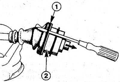
9 Remove, if present, the circlip using needle-nosed pliers and press the shaft out of the CV joint housing (see illustration).
12.9 Remove, if present, the circlip using needle nose pliers and press the shaft out of the CV joint housing
Installation
10. Thoroughly clean all parts with a rag.
11 Fit the rubber ring together with the bulk seal. Lubricate the end of the shaft with a thin layer of grease to facilitate installation.
12 Press the pivot sprocket onto the shaft shank.
13 Install the circlip. If there was no ring, then fasten the sprocket with three notches with a distance of 120°from each other, putting notches on the shaft splines (see illustration).
12.13 Install the circlip. If there was no ring, then fix the asterisk with three notches with a distance of 120°from each
14 Pack all of the supplied MOBIL CVJ 825 or MOBIL EXF 57 C grease into the (130 g) in the cuff and in the CV joint.
Ring spring version
15 Insert spacer 1 between the limit plate and the swivel sleeve (see illustration). The gasket can be made independently using the drawing.
12.15 Insert spacer 1 between limit plate and swivel sleeve
16 Fabricate a 2.5 mm thick gasket according to the drawing (see illustration).
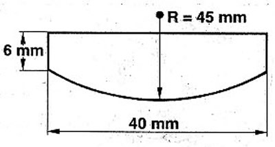
12.16 Gasket drawing
17 Press the stop plate back to its original position with a bronze punch and remove gasket 1.
18 Insert the ends of the collar into the grooves on the shaft and on the swivel sleeve.
19 Squeeze or unclench the joint so that the distance A between the cuff and the end of the joint coupling is 153.5±1 mm (see illustration).
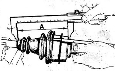
12.19 Compress or decompress the hinge so that the distance A between the collar and the end face of the hinge coupling is 153.5±1 mi
20 Insert a round punch between the collar and the swivel sleeve to equalize the pressure.
Attention! During installation, the cuff is often depressed, which leads to the creation of a vacuum inside the CV joint, which, during movement, draws one corrugation rib inward. Therefore, before installing the annular spring, it is necessary to remove air from under the cuff.
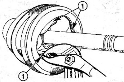
21 Fit the annular spring.
Attention! When landing, there should be no increase in the spring. When properly seated, the spring rings should touch each other.
Option with metal cuff
22 Slide on the metal Sleeve so that the guide lightly touches the swivel sleeve. In this position of the cuff, fasten it with notches at three points (see illustration).
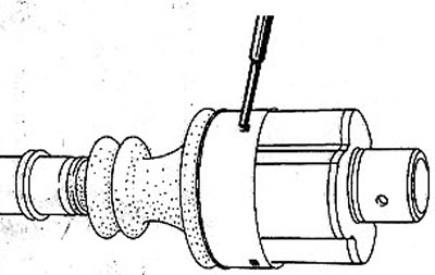
12.22 Secure the cuff with the notches at three points
23 Squeeze or unclench the joint so that the distance A between the cuff and the end of the joint coupling is 156±I mm (see illustration).
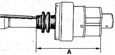
12.23 Compress or decompress the hinge so that the distance A between the collar and the end of the hinge coupling is 156±1 mm
24 Insert a round punch between the collar and the swivel sleeve to equalize the pressure.
25 Attach a new clamp to the small diameter of the cuff and tighten it with pliers, eg HAZET 1847-1.
Left drive shaft joint with ball bearing collar
Removing
Removing the cuff from this joint is carried out in the same way as for a joint without a bearing.
26 Using a press, press the shaft out of the pivot sprocket.
27 Using a press, press the shaft out of the bearing' on the small collar diameter.
Installation
28 Press on the collar with the bearing. In order not to damage the outer joint, attach a suitable clip to groove G of the drive shaft (see illustration).
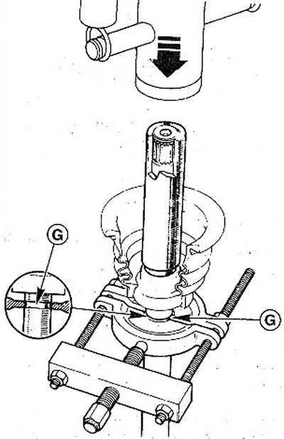
12.28 Press on the collar with the bearing
Attention! It is not allowed to stuff the bearing with a hammer. This will cause deformation of the bearing, which will cause leakage and rapid wear. For this reason, press the bearing slowly and carefully.
29 When pressing on the bearing, keep the distance L between the end face of the bearing and the end of the shaft (see illustration). This distance is 118 mm±0.2 mm. For vehicles with a 2.0 liter engine, 123.2 mm±0.2 mm.
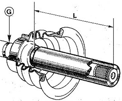
12.29 When pressing on the bearing, keep the distance L between the end face of the bearing and the end of the shaft
The subsequent installation of the cuff is carried out in the same way as for a CV joint without a bearing.