
Removing
1. Place the vehicle on jack stands.
2. Disconnect a reception pipe from a final collector.
3. Disconnect from a transmission draft of a gear change.
4. Unscrew on both sides of the car the bolts of the brackets 1 of the hinged units and the brackets 2 on the transverse arm. On vehicles with a diesel engine with a turbocharger, disconnect the stabilizer mount 2, working from the top side of the transverse lever (see illustration).
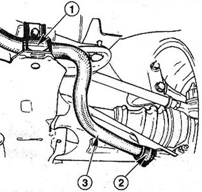
6.4 On both sides of the vehicle, unscrew the bolts securing the brackets 1 of the mounted units and the brackets 2 on the transverse arm
5. Remove stabilizer 3 together with rubber mounting pads (see illustration 6.4).
Installation
6. Check up a condition of rubber pillows before installation of the stabilizer. Replace porous or damaged pads with new ones.
7. Lubricate the rubber pads 2 with a thin layer of molybdenum grease and put in place with the stabilizer (see illustration 6.4). Bolts of fastening of arms screw in, but do not tighten finally.
Attention! Lubrication of support 1 of mounted units is not allowed. Otherwise, noises will be heard when driving, and the stabilizer may move.
8. Connect a reception pipe to a final collector.
9. Connect draft of a choice of transfers to a transmission.
10. Lower the car on wheels.
11. Tighten the stabilizer mounting bolts with a force of 35 Nm.
SCENIC cars
Differences in the removal and installation of the stabilizer.
12. Remove the engine mudguard.
13. Remove the catalyst.
14. Unscrew bolts of fastening and remove a longitudinal beam of a bearing frame.
15. Unscrew bolts of 2 collars of fastening of the right and left ends of the stabilizer (see illustration).
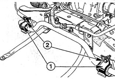
6.15 Unscrew the bolts 2 clamps fastening the right and left ends of the stabilizer
16. Remove the left and right support 1 stabilizer (see illustration 6.15).
17. Remove support 3 of lever 2 by unscrewing the nut (see illustration).
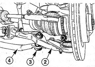
6.17 Remove support 3 of lever 2 by unscrewing the nut
18. Remove the anti-roll bar 4 (see illustration 6.17).
19. Lubricate support 3 of lever 2 with a thin layer of MOLYKOTE 33 MEDIUM grease before installation (see illustration 6.17).
Attention! Only these bearings are allowed to be lubricated.
20. Replace the anti-roll bar and secure it with a nut on the lever 2. The tightening torque of the nut is 20 Nm.
21. Fasten the clamps 2 to the ends of the stabilizer and to the transverse levers (see illustration 6.15). The tightening torque of the clamp bolts is 32 Nm.
Attention! Tighten the screw connections with the vehicle raised and firmly on the jack stands.
Installation of the remaining dismantled parts is carried out in the reverse order of removal.