
Removing
1. Unscrew the hub nut with the vehicle on wheels.
2. Remove the wheel brake caliper and secure with wire to the body.
Attention! Do not disconnect the brake fluid hose from the caliper. Otherwise, after installation, the brake system will need to be pumped.
Attention! The caliper must be fixed so that it does not sag and its weight does not stretch or twist the connected brake hose.
When dismantling the left drive shaft
3. Drain the gearbox oil.
4. Unscrew the three bolts 1 fastening the cuff of the inner CV joint to the gearbox (see illustration).
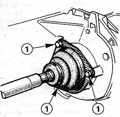
10.4 Unscrew the three bolts 1 fastening the cuff of the inner CV joint to the gearbox
When dismantling the right drive shaft
5. Knock out the spacer pin at the junction of the drive and satellite shafts using a 4 mm punch (see illustration).
10.5 Knock out the spacer pin at the junction of the drive and planetary shafts using a 4 mm punch
6. Vypressuyts pin of a spherical support of a tip of cross-section steering draft from the lever on a rotary fist, see the corresponding chapter.
7. Unscrew nuts of bolts of fastening of the lower part of an amortization rack to a rotary fist and take bolts.
8. Fasten the water shaft to the body with wire so that the shaft does not bend and the CV joints are not damaged when disconnected.
9. Press the driveshaft shank out of the hub using a suitable press or mandrel.
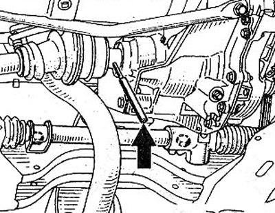
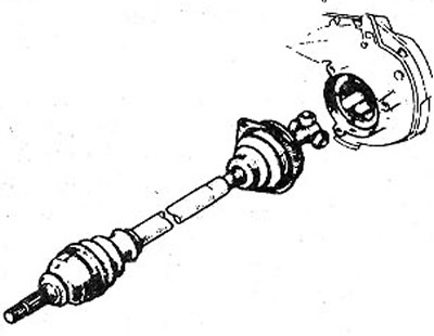
10. Move the steering knuckle out. In this case, the shaft shank will come out of the hole on the gearbox (see illustration). Then make sure that when performing this operation, the cuffs of the CV joints are not damaged.
10.10 Move the steering knuckle out. In this case, the shaft shank will come out of the hole on the gearbox
11. Remove the drive shaft from under the engine compartment.
Installation
New drive shafts are supplied with protective covers on the cuffs of the CV joints. These protective covers should be left until the installation of the drive shaft is completed. Even slight damage to the cuff of the CV joint will lead to the appearance of a crack and destruction of the CV joint.
12. Insert the left driveshaft CV joint into the hole on the transmission, keeping the shaft horizontal.
Right drive shaft
13. Lubricate the splines of the inner CV joint with a thin layer of molybdenum grease, such as MOLYKOTE BR2.
14. Insert the driveshaft shank into the splines of the gearbox opening, keeping the shaft horizontal. At the same time, align the angled pin with the holes of the drive and satellite shafts.
15. Insert two new spacer pins and drive them in with an appropriate punch (see illustration). Then seal the holes for the expansion pins with a liquid sealing compound such as CAF 4/60 THIXO or CUR1L.
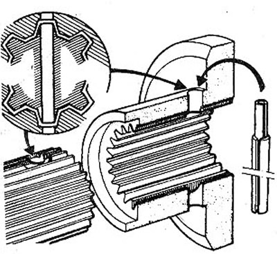
10.15 Insert two new spacer pins and hammer them in with a suitable punch
16. Apply LOCTITE SCEBLOC protective grease to the splines of the drive shaft shank, having previously cleaned and degreased them, for example, with a rag soaked in alcohol (see illustration).
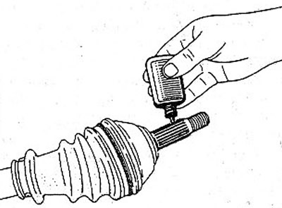
10.16 Apply LOCTITE SCEBLOC protective grease to the splines of the driveshaft shank, having previously cleaned and degreased them, for example, with a rag soaked in alcohol
17. Put a rotary fist and a nave on a shank of a power shaft. If necessary, use an appropriate mandrel to pull the shank into the hub.
Attention! If a suitable tool is not available to retract the shank into the hub, then after the shank has been inserted into the hole in the hub, retract it by screwing on the hub nut. After that, unscrew the hub nut again and screw it on again, installing the washer. Do not completely tighten the hub nut.
18. Fix on a rotary fist two bolts the lower part of an amortization rack. Screw new self-locking nuts onto the bolts and tighten them with a force of 17011m.
Attention! The bolts in the holes should be installed from front to back with the bolt heads facing in the direction of travel.
19. Install the tie rod end ball joint pin on the steering knuckle arm and screw a new self-locking nut onto it with a force of 35 Nm.
Left drive shaft
20. Clean the seating surface of the CV joint collar on the gearbox.
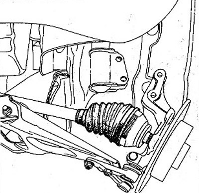
21. Fix on a transmission a cuff and a fixing plate, having aligned them horizontally. Bolts of fastening of a cuff tighten with application of force of 25 Nm (see illustration).
10.21 Attach the collar and mounting plate to the gearbox, aligning them horizontally
22. Fill in gear oil in a transmission.
23. Replace the brake caliper, see the relevant chapter.
24. Install those wheel, being guided by marks made at removal, and screw in wheel bolts.
25. Lower the vehicle onto the wheels and tighten the wheel bolts in a criss-cross pattern to 90 Nm.
26. Remove, if new drive shafts were installed, protective covers from the cuffs of the CV joints.
27. Shift into gear, have an assistant hold down the brake pedal and tighten the new hub nut to 250 Nm.