
Withdrawal (wheel side work)
Place the car on a two post lift.
Remove the xenon headlight range control sensor rod (if they are installed).
Remove the left front wheel.
Loosen the hub nut using the tool (Rou. 604-01).
Disconnect the wiring harness from the wheel speed sensor.
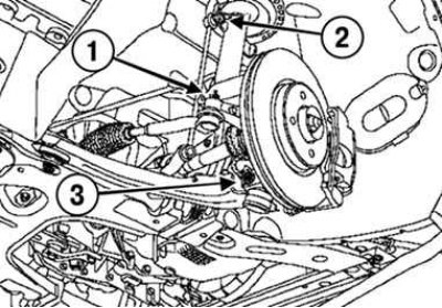
Pic. 3.175. Removing the left wheel drive shaft components: 1 – a finger of a spherical hinge of a tip of steering draft; 2 – a finger of the top hinge of a rack of the anti-roll bar; 3 – a bolt of fastening of a spherical support of the suspension arm
Loosen the nut securing the ball joint pin of the tie rod end (pic. 3.175);
Remove:
- the ball joint of the steering rod tip from the rotary knuckle with the help of a device (Tav. 476);
- nut of fastening of a finger of the top hinge of a rack of the anti-roll bar (see fig. 3.175);
- mounting bolt of the ball bearing of the suspension arm (see fig. 3.175).
Move the drive shaft away from the steering knuckle by turning the steering knuckle.
Remove the splined shank of the outer shaft joint from the hub.
Work carried out on the gearbox side
Drain the gearbox oil.
Disconnect the wheel drive shaft from the gearbox.
Note. Check the condition of the differential flange seal seat and, if necessary, replace it.
Without removing the protective cover, apply MO-LYKOTE BR2 grease to the splines of the inner joint shank.
Insert the splined shank of the inner shaft joint into the side gear.
Connect the wheel drive shaft to the hub.
The shaft shank must freely enter the gear for a length sufficient to wrap the hub nut.
Installation is made in an order, the return to removal.
Torque tighten:
- wheel bolts (110 Nm);
- hub nut (280 Nm);
- nut of fastening of a finger of a ball joint of a tip of steering draft (37 Nm);
- nut of fastening of a finger of a spherical support of the suspension arm (62 Nm);
- the nut of fastening the pin of the ball joint of the stabilizer bar (44 Nm);
- intermediate support mounting bolts (44 Nm).
Fill the gearbox with oil and top up the level.