
Remove:
- engine undertray protection;
- left front wheel.
Install an oil collection container.
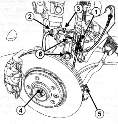
Disconnect:
- wiring harness (1) wheel speed sensor;
- brake hose (2).
Remove:
- fastening bolt (3) brake hose bracket and wheel speed sensor harness;
- brake hose and wheel speed sensor harness bracket;
- hub nut (4), by locking the hub with the hub lock (Rou. 604-01);
- fastening nut (5) ball joint pin of the tie rod end;
- tie rod end ball joint with ball joint pin extractor (Tav. 476);
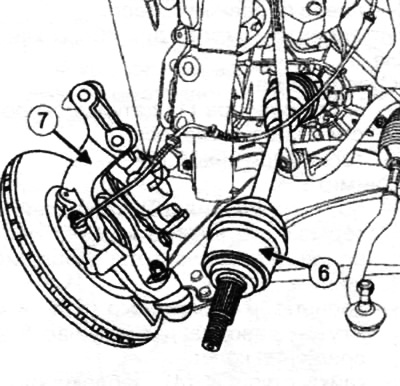
- bolts and nuts (6) attaching the shock absorber to the steering knuckle.
Slide the wheel drive shaft away from the hub axle.
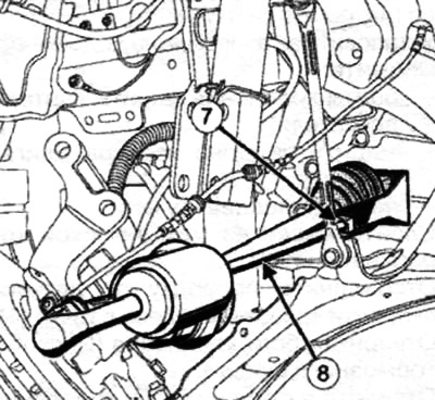
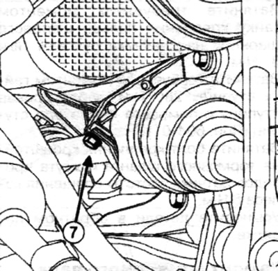
Remove the front left wheel drive shaft from the automatic transmission using a wheel drive snap shaft puller (Tav. 1813) (7) and punches (Emb. 880) (8).
Note. Replace the steering shaft universal joint yoke clamp nut and the differential flange seal.
If there is a locking compound in the splines of the universal joint and on the nut of its fastening when removing, apply a locking compound to the splines of the universal joint and on the nut of its fastening during installation.
Insert the wheel drive shaft into the gearbox as horizontally as possible.
Insert the wheel drive shaft into the steering knuckle.
Note. The wheel drive shaft must freely enter the steering knuckle and protrude from it to a length sufficient to install the hub nut.
Torque tighten the shock absorber mounting bolts 180 Nm.
Insert the ball joint pin of the tie rod end into the steering knuckle.
Torque tighten the tie-rod end ball joint pin nut 37 Nm.
Torque tighten the hub nut 280 Nm, locking the hub with the hub lock (Rou. 604-01).
Tighten the brake hose bracket and wheel speed sensor harness bolt to 8 Nm.
Install the parts in reverse order. Left front wheel drive shaft (cars with manual gearbox)
Place the car on a lift.
Remove:
- engine crankcase mounting bolts;
- engine undertray protection;
- left front wheel.
Drain the oil from the manual transmission.
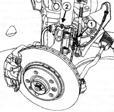
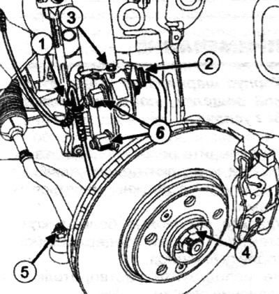
Disconnect the wiring from the wheel speed sensor at the point (1). Loosen the mounting bolt (2) brake hose clamps.
Move aside the brake hose bracket.
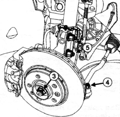
Remove:
- hub nut (3), by locking it with the hub lock (Rou. 604-01);
- nut of fastening of a finger of a ball joint of a tip of steering draft (4).
Remove the tie rod end ball joint using a ball joint pin extractor (Tav. 476).
Turn away bolts (5) attaching the shock absorber strut to the steering knuckle.
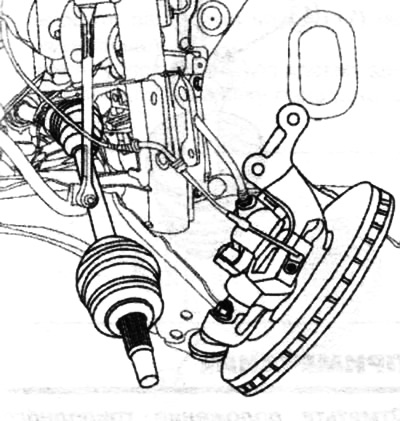
Push out the left front wheel drive shaft (6) from the hub axle (7).
Remove the left front wheel drive shaft from the wheel side.
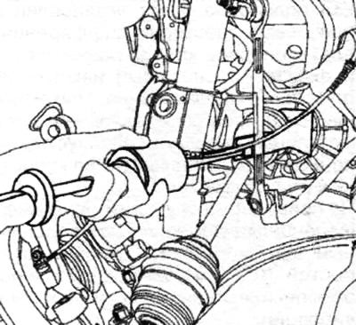
Pull the front left drive shaft out of the manual transmission with a punch (Emb. 880) and puller (Tav. 1813).
Remove:
- drive shaft of the left front wheel;
- sealing collar of the flange of the left differential.
Note. The wheel drive shaft must freely enter the steering knuckle and protrude from it by a mine, sufficient to install the hub nut.
Torque tighten the shock absorber mounting bolts 180 Nm.
Insert the ball joint pin of the tie rod end into the steering knuckle.
Torque tighten the tie-rod end ball joint pin nut 37 Nm.
Torque tighten the hub nut 280 Nm, locking the hub with the hub lock (Rou. 604-01).
Tighten the brake hose bracket and wheel speed sensor harness bolt to 8 Nm.
Adopt the details in reverse order.
Right front wheel drive shaft (vehicles with automatic transmission) Place the car on a lift.
Remove:
- engine undertray protection.
- right front wheel.
Drain the automatic transmission fluid.
Disconnect:
- wiring harness (1) wheel speed sensor;
- brake hose (2).
Remove:
- fastening bolt (3) brake hose bracket and wheel speed sensor harness;
- brake hose and wheel speed sensor harness bracket;
- hub nut (4), by locking the hub with the hub lock (Rou. 604-01);
- fastening nut (5) ball joint pin of the tie rod end;
- tie rod end ball joint with ball joint pin extractor (Tav. 476);
- bolts and nuts (6) attaching the shock absorber to the steering knuckle.
Slide the wheel drive shaft away from the hub axle.
Remove the front left wheel drive shaft from the automatic transmission using a puller (Tav. 1813) (7) and punches (Emb. 380).
Remove:
- bolt (7) fixing the intermediate support of the wheel drive shaft;
- right front wheel drive shaft.
Note. Replace the steering shaft universal joint yoke clamp nut and the differential flange seal.
If there is a locking compound in the splines of the universal joint and on the nut of its fastening when removing, apply a locking compound to the splines of the universal joint and on the nut of its fastening during installation.
Insert the wheel drive shaft into the gearbox as horizontally as possible.
Insert the wheel drive shaft into the steering knuckle.
Torque tighten the intermediate support mounting bolt 21 Nm.
Note. The wheel drive shaft must freely enter the steering knuckles and protrude from it to a length sufficient to install the hub nut.
Torque tighten the shock absorber mounting bolts 180 Nm.
Insert the ball joint pin of the tie rod end into the steering knuckle.
Torque tighten the tie-rod end ball joint pin nut 37 Nm.
Torque tighten the hub nut 280 Nm, locking the hub with the hub lock (Rou. 604-01).
Tighten the brake hose bracket and wheel speed sensor harness bolt to 8 Nm.
Install the parts in reverse order.