



Contents: Removal 🠛 Installation 🠛
Removal
Remove the wheel drive shaft from the appropriate side.
Remove the wheel drive shaft covers.
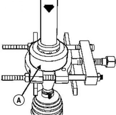
Fig. 3.185. Pressing of large vibration damper A using a press
Press the large vibration damper A with a press, using the puller as a support (fig. 3.185).
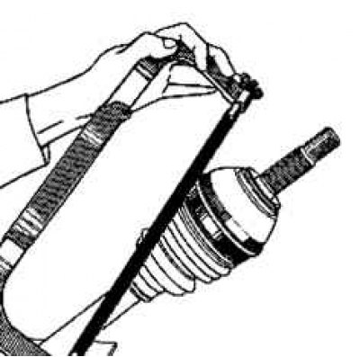
Fig. 3.186. Removing the large and small clamps
Cut the large and small clamps, being careful not to damage the grooves of the hinge housing and drive shaft (fig. 3.186).
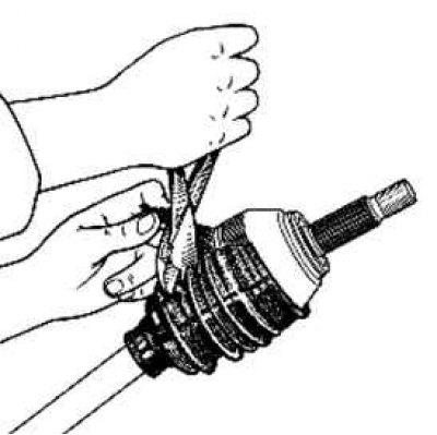
Fig. 3.187. Cutting the cover
Cut the cover along its entire length. Remove as much grease as possible (fig. 3.187).
Caution! Make sure that the blows are applied to the front end of the clip, and not to the ball races.
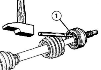
Fig. 3.188. Removing the clip: 1 – clip
Using a hammer and punch, strike the collar several times to disengage the joint housing from the drive shaft (fig. 3.188).
Remove the retaining ring and protective cover.
Installation
Place the boot on the drive shaft from the gearbox side.
Caution: Do not use solvents to clean the hinge parts.
Note: Observe the amount of grease placed in the joint as specified in Table 3.2.
Apply a small amount of T857740131 grease to the bore under the large vibration damper.
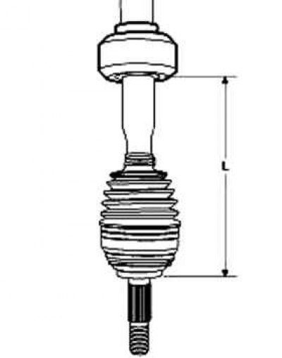
Fig. 3.189. Pressing the large vibration damper onto the drive shaft of the wheel
Using a press, press the large vibration damper onto the wheel drive shaft until the dimension L = 221 mm + 3 is obtained (fig. 3.189).
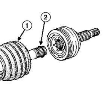
Fig. 3.190. Installing the cover: 1 – case; 2 – retaining ring
To facilitate installation of the protective cover, lightly lubricate the wheel drive shaft (fig. 3.190).
Install on the drive shaft:
- small diameter clamp;
- protective case;
- new retaining ring.
Using a brass drift, tap the hinge body to insert the collar until the retaining ring snaps into place behind the collar.
Attention! The retaining ring must be replaced every time the hinge housing is removed.
Fill the boot and outer joint housing with grease in equal quantities.
Position the edges of the protective boot in the grooves of the joint housing and drive shaft.
Rock the CV joint manually to check that the boot belts are installed correctly.
Insert a rod with rounded edges between the boot and the hinge body to adjust the amount of air inside the hinge.
Install the large clamp.
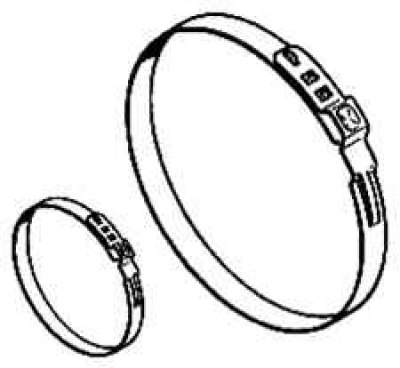
Fig. 3.191. Large and small clamps
Tighten the small and large clamps on the cover until they snap into place using the tool (Tav. 1168) (fig. 3.191).
Tighten the clamps.
Place the spacer A in the lower notches and squeeze the pliers until they stop. The pre-crimped clamp can slide on the protective cover. Position it in the desired location.
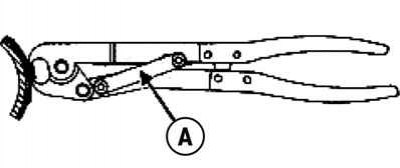
Fig. 3.192. Compression of clamps
Place spacer A into the upper notch and squeeze the pliers until they stop (fig. 3.192).
Install the wheel drive shaft on the appropriate side.