



Contents: Removal 🠛 Installation 🠛
Removal
Drain the oil from the gearbox.
Place the vehicle on a two-post lift.
Remove the engine oil pan guard and the left front wheel.
Disconnect the wire connector from the wheel speed sensor.
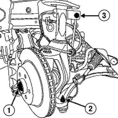
Fig. 3.176. Removing the fasteners of the left wheel drive shaft components: 1 – hub nut; 2 – tie rod end pin fastening nut; 3 – nut for fastening the pin of the upper ball joint of the anti-roll bar
Unscrew the hub nut using the tool (Rou. 604-01), tie rod end pin mounting nut and stabilizer bar upper ball joint mounting nut (fig. 3.176)
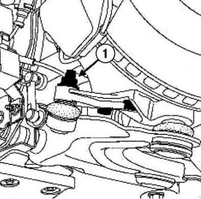
Fig. 3.177. Lower reaction rod fastening nut: 1 – nut
Loosen the lower reaction rod mounting nut (fig. 3.177).
Compress the suspension by approximately 10 cm. Remove the ball joint of the suspension arm.
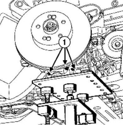
Fig. 3.178. Steering knuckle support mounting bolts: 1 – bolts
Remove the steering knuckle support mounting bolts (fig. 3.178).
Unload the suspension by raising the lift by 50 cm. Remove the subframe reinforcement bar.
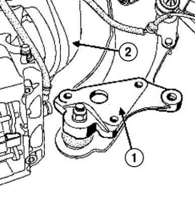
Fig. 3.179. Separation of the support: 1 – support; 2 – steering knuckle
Separate the steering knuckle from the support using hammer blows (fig. 3.179).
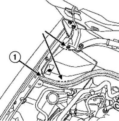
Fig. 3.180. Removing the seal: 1 – seal
Remove the seal and cut the hatch at the points shown by the arrow in Figure 3.180.
Remove the plastic rivets from the hatch cover.
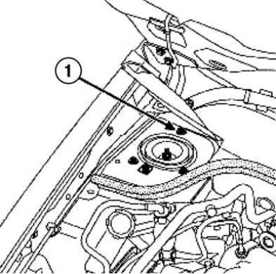
Fig. 3.181. Shock absorber support mounting bolt: 1 – bolt
Loosen the shock absorber support mounting bolt (fig. 3.181).
Instead of the bolt, screw in an M8x30 bolt so that the head does not protrude by 20 mm.
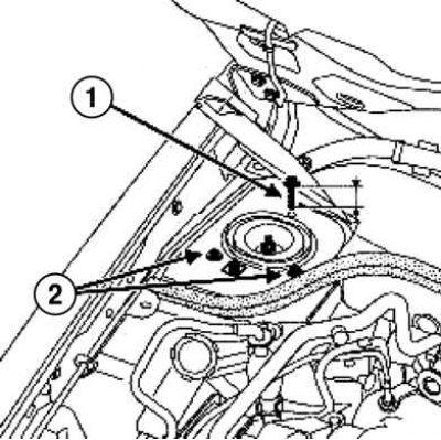
Fig. 3.182. Installing the auxiliary bolt on the support: 1 – bolt M8x30; 2 – shock absorber support mounting bolts
Remove the shock absorber support mounting bolts (fig. 3.182).
(Original version on our portal: «RENAULTBOOK.ru»)
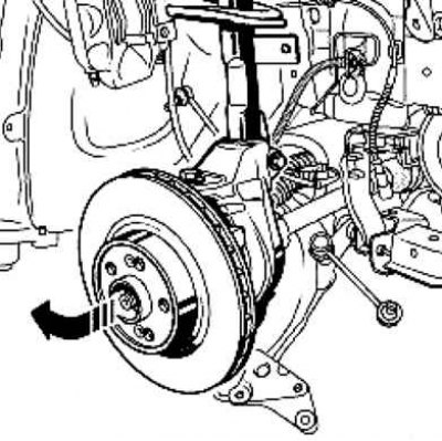
Fig. 3.183. Removing the "shock absorber strut - spring - steering knuckle" assembly
Move the shock absorber strut - spring - steering knuckle assembly to the side (fig. 3.183).
Remove the wheel drive shaft from the hub.
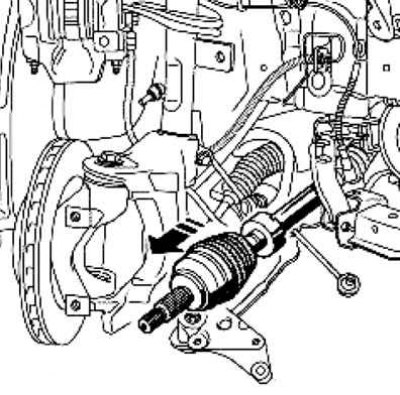
Fig. 3.184. Removing the wheel drive shaft from the gearbox
Disconnect the wheel drive shaft from the gearbox (fig. 3.184).
Installation
Without removing the protective cover, apply MOLYKOTEBR2 grease to the splines of the inner joint tailstock.
Insert the splined shank of the inner joint of the shaft into the axle gear.
Connect the wheel drive shaft to the hub.
The shaft tail must freely enter the gear to a length sufficient to tighten the hub nut.
Installation is carried out in the reverse order of removal.
Insert the mounting tab into the socket.
Fill the gearbox with oil and bring its level to the norm.
Tighten to the specified torque:
- shock absorber support mounting bolts (21 Nm);
- bolts for fastening the steering knuckle to the support (72 Nm);
- nut for fastening the ball joint pin of the suspension arm (100 Nm);
- brake caliper guide pin mounting bolts (170 Nm);
- nut for fastening the ball joint pin of the anti-roll bar (44 Nm);
- nut for fastening the ball joint pin of the steering rod end (37 Nm);
- hub nut (280 Nm);
- wheel bolts (130 Nm).