
- The drive shaft can be partially repaired by replacing the outer joint or the outer joint boot.
- Remove the drive shaft. on which the protective cover needs to be replaced.
- Cut the clamps and the elastic corrugated protective cover along the entire length and remove the grease from it.
- Remove the elastic corrugated protective cover.
- Spread the ends of the retaining ring apart (1. fig. 8.11) and at the same time hit the open end of the inner race (2) a hammer with a striker made of soft material.
- Separate the joint from the shaft.
- Install a small clamp and a protective cover on the drive shaft, sliding it from the gearbox side

Pic. 8.10. Constant velocity joint on the outside of the drive shaft: 1 - outer hinge housing;; 2 - drive shaft;; 3 - corrugated cover;; 4 - balls;; 5 - inner race;; 6 - separator;; 7 - retaining ring
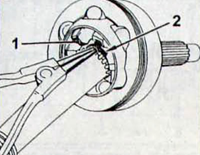
Pic. 8.11. Removing the inner race of the constant velocity joint: 1 - inner race; 2 - retaining ring
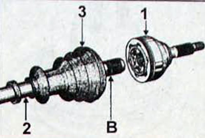
Pic. 8.12. Installing a constant velocity joint on the drive shaft: 1 - constant velocity joint; 2 - drive shaft; 3 - corrugated cover; B - groove
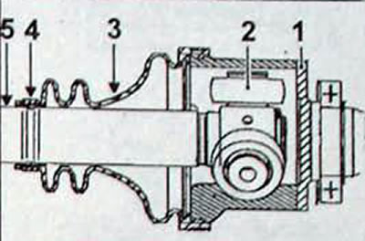
Pic. 8.13. Drive shaft inner joint: 1 - body; 2 - triaxial roller support; 3 - protective cover; 4 - clamp; 5 - drive shaft
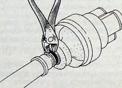
Pic. 8.14. Cutting the clamp securing the elastic corrugated protective cover to the drive shaft
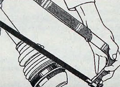
Pic. 8.15. Sawing the clamp securing the protective cover to the hinge body
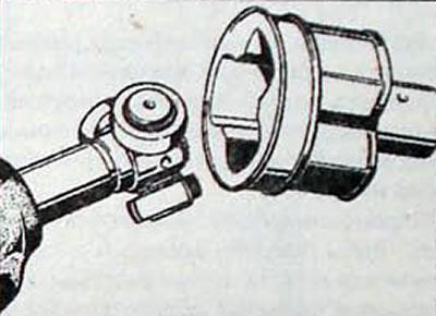
Pic. 8.16. Removing the constant velocity joint housing
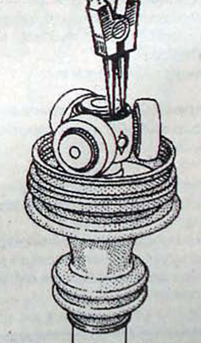
Pic. 8.17. Removing the retaining ring securing the triaxial roller support of the tripod CV joint
- Slide the joint along with the new snap ring along the shaft splines until the snap ring fits into the shaft groove (pic. 8.12).
- Fill the boot and the outer joint housing with lubricant in equal quantities.
- Place the edges of the protective boot into the grooves on the body (1, fig. 8.10) outer joint and drive shaft (2).
- Install a large clamp.
- Using special pliers, tighten the clamp securing the protective cover.
Note. CAILLAU locking clamps cannot be reused.