
Removal
- Remove the drive shaft. on which the protective cover needs to be replaced
- Cut the clamp securing the elastic corrugated protective cover to the drive shaft.
- Saw the clamp securing the elastic corrugated protective cover to the constant velocity joint body, without damaging the groove on the joint body.
- Cut the protective cover.
- Remove as much grease as possible.
- Remove the constant velocity joint housing from the drive shaft.
Attention
- The hinge body is not equipped with a locking ring, so it can be removed without effort.
- When removing the constant velocity joint housing from the drive shaft, be careful not to remove the rollers from the spider.
- Do not use solvents to clean hinge parts.
- Using special pliers, remove the retaining ring securing the triaxial support of the tripod CV joint rollers.
- Using a press and a special device, squeeze the drive shaft out of the triaxial support of the tripod CV joint rollers.
Installation
- Lubricate the drive shaft and put two clamps and a protective cover on it
- Using a tubular mandrel of the appropriate diameter, install the triaxial support of the tripod CV joint rollers on the drive shaft
- Install the retaining ring securing the triaxial roller support of the tripod CV joint.
- Place the lubricant in an elastic corrugated protective cover and distribute it evenly inside the cover.
- Install the constant velocity joint housing onto the drive shaft.
- Insert a smooth rod with a rounded end into the boot and drive shaft to release «excess» air from the case.
- Move the joint body along the shaft like this. to obtain dimension A = 156±1 mm between the end of the cover and the area of the largest diameter of the machined surface of the hinge body (rice. 8.9).
- In this position, remove the rod.
- With special pliers T. Av. 1034 tighten the small clamp securing the protective cover. To tighten the large clamp securing the protective cover, you must use OETIKER pliers.
- Install the drive shaft.
RC 490 Right Drive Shaft Inner Joint - JC Transmission
Removal
- Use pliers to rip out the casing in three places (rice. 8.21).
- Cut the clamp and the elastic corrugated protective cover along its entire length.
- Remove as much grease as possible.
- Remove the cover.
- Remove the constant velocity joint housing from the drive shaft (rice. 8.16).
Attention.
- The hinge body is not equipped with a locking ring, so it can be removed without effort.
- When removing the constant velocity joint housing from the drive shaft, be careful not to remove the rollers from the spider.
- Using special pliers, remove the retaining ring securing the triaxial roller support of the tripod CV joint (rice. 8.17).
- Using a press and a special device, squeeze the drive shaft out of the triaxial roller support of the tripod CV joint (rice. 8.18).
Installation
- Lubricate the drive shaft and place a clamp and elastic corrugated protective cover on it (2, fig. 8.22) with metal insert (3) and casing (1).
- Using a tubular mandrel of the appropriate diameter, install the triaxial support of the tripod CV joint rollers on the drive shaft (rice. 8.19).
- Install the retaining ring for fastening the triaxial support of the tripod CV joint rollers or caulk it at three points through 120°, rolling the metal onto the splines of the drive shaft.
- Place the lubricant in an elastic corrugated protective cover and distribute it evenly inside the cover.
Note. The amount of lubricant added must strictly correspond to that specified in the chapter «Technical data».
- Install the cover and metal insert into the housing.
- Install the housing by moving it until it touches the collar on the hinge body.
- In this position, fix the casing on the hinge body by punching in three holes on the casing (rice. 8.23).
- Insert a smooth rod with a rounded end between the boot and the drive shaft to release «excess» air from the case.
- Move the joint body along the shaft like this. to obtain dimension A = 156±1 mm between the end of the cover and the area of the largest diameter of the machined surface of the hinge body (rice. 8.24).
- In this position, remove the rod.
- With special pliers T. Av. 1034 tighten the clamp securing the protective cover.
- Install the drive shaft.
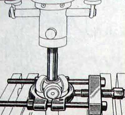
Pic. 8.18. Using a press and a special device for squeezing the drive shaft out of the triaxial roller support of a tripod CV joint
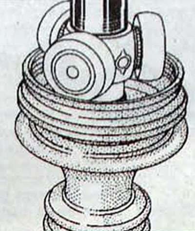
Pic. 8.19. Installing a triaxial support for tripod CV joint rollers on the drive shaft
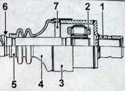
Pic. 8.20. Right drive shaft inner joint RC 490: 1 - hinge body; 2 - triaxial roller support; 3 - casing; 4 - protective cover; 5 - clamp; 6 - drive shaft; 7 - metal insert
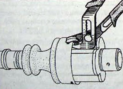
Pic. 8.21. Using pliers to caulk the constant velocity joint housing
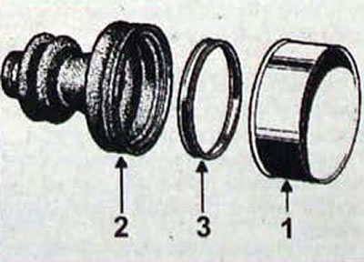
Pic. 8.22. Protective case (2), insert (3) and casing (1) inner CV joint RC 490 right drive shaft
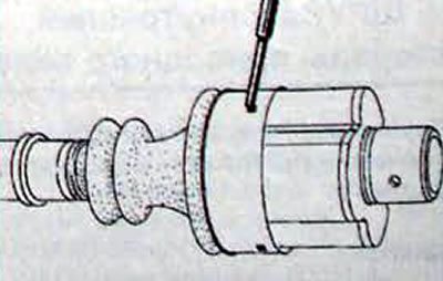
Pic. 8.23. Fixing the casing on the body of the constant velocity joint
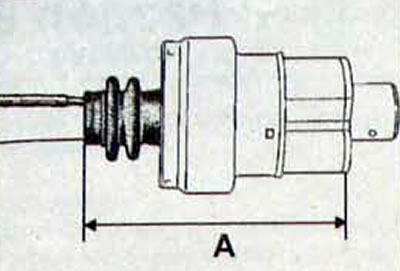
Pic. 8.24. Measuring the distance between the end of the cover and the area of the largest diameter of the hinge body: A = 156±1 mm