
2. Cut the mounting collars of the protective boot and slide the boot to the outer CV joint.
3. Remove as much grease as possible from the CV joint and determine the type of CV joint.
Ball joint (AC 1700)
1. Using special pliers, open the inner retaining ring of the CV joint. At the same time, tap the open surface of the joint cage with a mallet to separate the CV joint from the drive shaft. Remove the protective cover and rubber band.
2. Clean the CV joint using kerosene or a suitable solvent and dry it. Examine the CV joint.
3. Move the CV joint from side to side to access each ball in turn (above). Inspect the balls for cracks, flat spots, and pitting.
4. Examine the routes of the balls on the body and holder of the CV joint. If the runs are wider, the balls will no longer sit tight in them. Check the CV joint separator slots for signs of wear and cracks.
5. If any of the CV joint components are worn or damaged, the complete driveshaft assembly must be replaced as none of the components are sold separately. If the condition of the CV joint is satisfactory, purchase a repair kit consisting of a new protective boot, rubber collar, retaining spring and grease.
6. Tape the grooves at the end of the drive shaft, then install the rubber collar and protective boot onto the shaft. Attach the inner end of the cover with a collar.
7. Remove the tape, then install the CV joint on the drive shaft (The inner retaining ring must fit into the shaft groove).
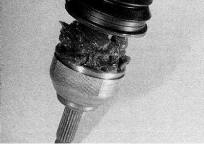
8. Make sure the retaining ring securely holds the CV joint to the drive shaft, then fill the joint with grease. Make sure that grease gets into all ball paths and place excess grease in a protective bag.
9. Place the outer sealing lip of the protective boot into the groove on the CV joint housing. Raise the edge of the boot to equalize the air pressure. Install the clamps on the cover and tighten them.
10. Make sure that the SHRUS moves freely in all directions, then install the drive shaft as described in Section Removal and installation of a power shaft.
CV joint with cross (GE86)
1. Remove the inner CV joint, bearing and protective cover, as described in Section Replacing the protective cover of the inner CV joint of the right drive shaft (models with manual transmission) or Replacing the protective cover of the inner CV joint of the left drive shaft (models with manual transmission) of this Chapter.
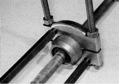
2. Where the vibration damper is installed, mark its orientation as well as its position on the drive shaft, then using a puller or press, remove it from the inside end of the drive shaft (refer to accompanying illustration). Make sure that the puller legs only touch the inner rubber bushing of the vibration damper, otherwise the vibration damper will be skewed.
3. Remove the cover of the outer CV joint from the inner end of the drive shaft.
4. Clean the outer CV joint using kerosene or a suitable solvent and dry it. Examine the CV joint.
5. Check the driveshaft cross and pivot pin for signs of wear, pitting, and abrasions. Make sure that the half-hinge turns easily and smoothly, without jerks.
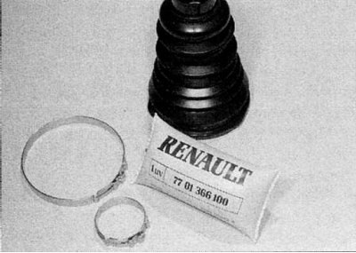
6. If wear or damage is found, replace the drive shaft as none of the components are sold separately. If the condition of the CV joint components is satisfactory, purchase a repair kit of parts, consisting of a new protective cover, mounting clamps and grease (refer to accompanying illustration).
7. Tape the grooves on the inner end of the drive shaft with adhesive tape, then carefully place the outer protective boot on the shaft.
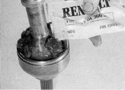
8. Fill the CV joint with grease (refer to accompanying illustration) and place the excess in a protective case.
9. Close the CV joint with a cover and make sure that its sealing edges fall into the grooves of the drive shaft and half-joint (refer to accompanying illustration). Make sure the CV joint moves freely in all directions.
10. Moisten the drive shaft with soapy water. Install the vibration damper on the shaft using a hollow drift, which should only rest against its inner sleeve. Use marks made before removal.
11. Install the components of the inner CV joint as described in Section Replacing the protective cover of the inner CV joint of the right drive shaft (models with manual transmission) or Replacing the protective cover of the inner CV joint of the left drive shaft (models with manual transmission), then install the drive shaft (refer to section Removal and installation of a power shaft).