
2. Two types of CV joints are used on these models: Gl62 and RC490. Hinges can be distinguished by the shape of their body. The body of the CV joint Gl62 is smooth, round; the RC490 hinge has recesses - from the end, the body resembles a trefoil.
CV joint GL62
1. Cut the mounting straps, then slide the protective boot down the shaft.
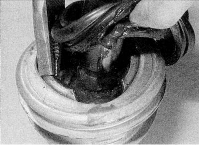
2. Using pliers, carefully pry up the locking tabs located at the corners of the bonding plate (refer to accompanying illustration). Separate the CV joint housing from the tripod. Hold the rollers, otherwise they may come off the tripod. After removing the half-hinge, fix the rollers in the working position with adhesive tape.
Note. The rollers make up matched pairs with their supports, so it is important not to confuse them.
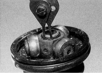
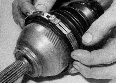
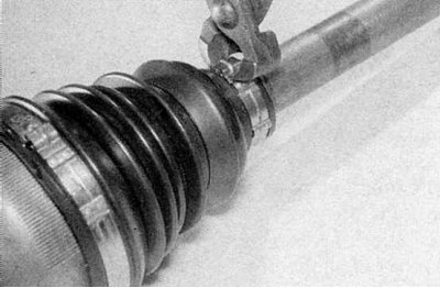
3. Using special pliers, remove the retaining ring that secures the tripod to the drive shaft (refer to accompanying illustration). Please note that on some models the CV joint can be fixed with a blocking rim; in this case, detach the hinge using a file. Mark the position of the CV joint tripod on the drive shaft.
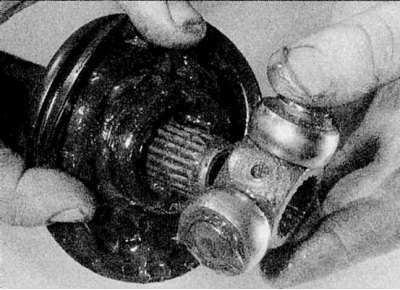
4. Remove the tripod (refer to accompanying illustration). If this fails, use a puller. Make sure that the puller feet are behind the tripod and not touching the tripod rollers. Alternatively, a hydraulic press can be used.
5. Remove the protective boot and inner locking collar from the end of the drive shaft.
6. Wipe the components of the CV joint, being careful not to erase the marks made during removal. Do not use any solvents for cleaning.
7. Inspect the tripod, rollers and CV joint housing for nicks and signs of wear. Make sure the rollers rotate easily and smoothly on the rods. If the tripod or casters are worn, the assembly can be replaced. The CV joint housing is not sold separately. Purchase a repair kit that includes a protective boot, shoulder/retainer spring, and special grease.
8. Tape the slots on the end of the drive shaft with tape, then carefully install the inner locking collar and protective boot onto the shaft.
9. Remove the tape, then, using the marks made during removal, install the tripod into the grooves of the drive shaft. Using a hammer and a soft metal drift, drive the tripod into working position, being careful not to damage the grooves of the shaft or the rollers of the CV joint. Alternatively, use a hydraulic press with the drive shaft supported.
10. Secure the tripod with the retaining ring, making sure it fits into the driveshaft groove. Where a circlip is not used, secure the end of the drive shaft with a hammer and punch by tapping it at three equidistant points.
11. Spread the lubricant evenly over the tripod and inside the CV joint housing. Put the rest of the grease in the protective cover.
12. Install the CV joint housing on the tripod.
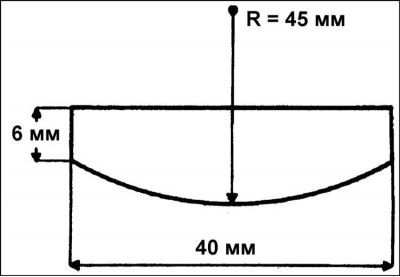
13. From 2.5 mm thick steel strip or similar material, make a base plate of the dimensions shown in the figure (refer to accompanying illustration).
14. Place a backing plate alternately under each locking tongue of the CV joint housing fastening plate and tap on the tongue. Remove the plate when all locking tabs return to their original shape.
15. Place the protective boot on the drive shaft. Install the edges of the boot into the grooves on the drive shaft and the CV joint housing.
16. Slide the inner locking bezel into place against the boot.
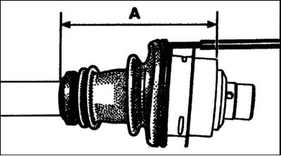
17. Using a blunt tool, carefully pry up the outer sealing lip of the boot to equalize the air pressure. Without removing the tool, squeeze the CV joint so that the distance from the inner end of the protective cover to the end of the hinge housing is 153 mm (refer to accompanying illustration). While holding the CV joint housing in this position, remove the tool from under the boot.
18. Install the clamps on the cover and tighten them.
19. Make sure the CV joint moves freely in all directions, then install the drive shaft (refer to section Removal and installation of a power shaft).
CV joint RC490
1. Bend the metal cover of the CV joint with pliers, where it is bent into the recesses of the hinge housing.
2. Cut the inner collar of the protective boot with wire cutters.
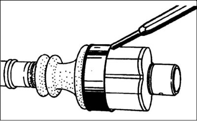
3. Using a soft metal drift, knock the cap off the hinge body (refer to accompanying illustration). Separate the CV joint housing from the tripod. Hold the rollers, otherwise they may come off. After removing the half-hinge, fix the rollers in the working position with adhesive tape.
Note. The rollers make up matched pairs with their supports, so it is important not to confuse them.
4. Remove the tripod and protective case assembly and inspect the components for signs of wear (refer to paragraphs above). Purchase a repair kit of parts, consisting of a protective cover, clamp, metal insert and CV joint cover, as well as special grease.
5. Install the metal insert into the inside of the protective boot, then place the protective boot assembly inside the metal CV joint cap.
6. Mount the tripod as described above.
7. Evenly distribute the special grease on the tripod and inside the CV joint housing. Fill the protective cover with the rest of the lubricant.
8. Set the CV joint housing to the working position on the tripod.
9. Slide the metal cover onto the CV joint housing. Attach the cover by driving the appropriate portions of the cover into the notches in the hinge body using a hammer and a rounded punch.
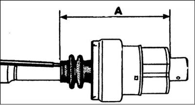
10. Using a blunt tool, gently pry up the inner sealing lip of the boot to equalize the air pressure. Without removing the tool, squeeze the CV joint so that the distance from the inner end of the protective cover to the end of the hinge housing is 156 mm (refer to accompanying illustration). While holding the CV joint housing in this position, remove the tool from under the boot.
11a. Install the clamp on the inner end of the protective boot.
11b. Tighten the clamp
12. Make sure that the SHRUS moves freely in all directions, then install the drive shaft as described in Section Removal and installation of a power shaft.