



Contents: Removal 🠛 Installation 🠛
Note: It is necessary to replace the "Nylstop" type nut with an "Enko" nut (installed without the use of a gripping compound). If the vehicle is already equipped with an "Enko" type nut, there is no need to replace it - it can be used four times. On models with a manual transmission, new roll pins securing the drive shaft to the differential will be required during installation.
Note: The outer CV joint grooves are coated with a gripping compound. Therefore, a puller will be required to remove the hub assembly from the end of the drive shaft.
Removal
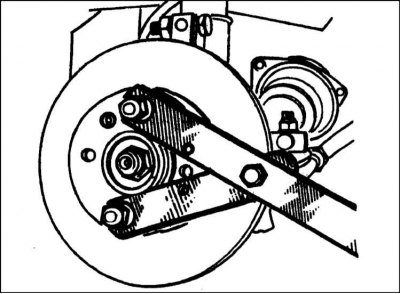
1. Remove the wheel cap/hub cap (where is available), then loosen the drive shaft nut and also the wheel bolts.
2. Block the rear wheels, apply the handbrake, then jack up the front of the car and place it on axle stands. Remove the front wheel.
3. On models equipped with ABS, remove the wheel speed sensor as described in Chapter Brake system.
4. Remove the drive shaft mounting nut. If the nut was not loosened before the vehicle was jacked up (refer to paragraph 1), install the two wheel bolts into the hub and tighten them securely. Have an assistant press the brake pedal firmly to lock the hub, then use a socket and extension rod to loosen and remove the nut. Alternatively, make a forked tool from two pieces of steel strip (one long, one short), connecting them with a bolt and nut. Attach the tool to the hub using two wheel bolts and, holding it thus stationary, unscrew the drive shaft mounting nut.
5. Remove the two bolts securing the brake caliper assembly to the steering knuckle and lift the assembly off the disc. Use a piece of wire or twine to tie the caliper to the front suspension spring, being careful not to pull on the brake hose.
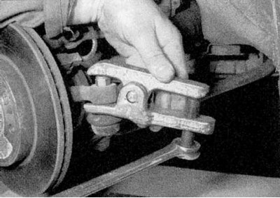
6. Loosen and remove the nut securing the ball joint of the tie rod end to the steering knuckle. Release the ball joint rod using a special puller (refer to the accompanying illustration).
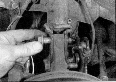
7. Loosen and remove the two nuts and their washers from the bolts that secure the steering knuckle to the strut. Note that the nuts are located on the back of the strut. Remove the top bolt, the bottom bolt should remain in the working position at this stage (refer to the accompanying illustration).
Left drive shaft - models with manual transmission
1. Drain the transmission oil as described in Chapter Maintenance.
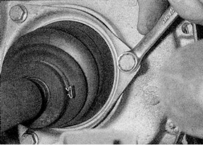
2. Loosen and remove the three bolts securing the protective boot plate to the transmission wall (refer to the accompanying illustration).
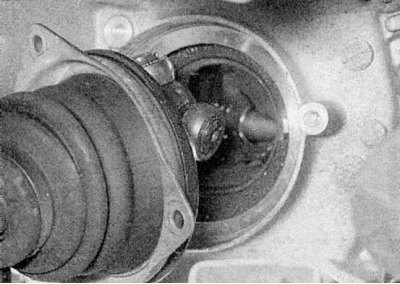
3. Move the top of the steering knuckle outward so that the CV joint tripod comes out of its housing (refer to the accompanying illustration). Be prepared for oil to come out and make sure the rollers don't fall off the tripod.
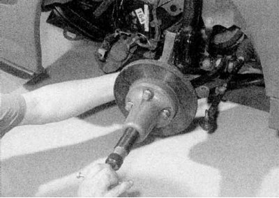
4. Remove the lower bolt securing the steering knuckle to the strut. Separate the outer CV joint from the hub and remove the drive shaft using a hammer and a soft metal drift. Have an assistant hold the hub while doing this and be careful not to damage the protective boots. If this method does not work, use a puller (refer to the accompanying illustration). Lock the hub assembly by inserting the bolts into the base of the strut.
Right drive shaft - models with manual transmission
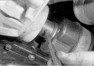
1. Rotate the drive shaft until the roll pins that secure the inner CV joint to the differential side gear shaft are visible. Using a hammer and 5mm punch, drive out the roll pins (refer to the accompanying illustration). New pins must be used during installation.
2. Pull the top of the steering knuckle outward to separate the inner CV joint from the differential side pinion shaft. Remove the sealing ring from the pinion shaft (where is available).
3. Remove the drive shaft as described above.
4. Pull the top of the steering knuckle outward and separate the inner CV joint from the drive flange.
5. Remove the drive shaft as described above.
Installation
1. Genuine Renault drive shafts are supplied in cardboard or plastic packaging to prevent damage to the protective covers. Even a slight impact on the cover can cause a puncture. If the removed drive shaft is not to be replaced, it is recommended to place it in a similar package, made of cardboard.
Left drive shaft - models with manual transmission
1. Wipe the walls of the transmission housing and the grooves of the outer CV joint.
2. Insert the CV joint tripod into its housing, keeping the drive shaft horizontal. Align the holes in the protective boot mounting plate with the holes in the differential housing. Install the mounting bolts and tighten them to the torque specified in the Specifications. Make sure that the protective boot is not twisted.
3. Clean and dry the hub and outer CV joint grooves and apply gripping compound to the drive shaft grooves (Renault recommends Lostite Scelbloc).
4. Move the top of the steering knuckle inward, guiding the drive shaft into the hub.
5. Push the drive shaft all the way into the hub, then insert the two suspension strut mounting bolts (from the front of the car). Install washers and nuts on the bolts and tighten them to the specified torque Specifications by the efforts of the Head Suspension and steering).
6. Clean the threads of the caliper bracket mounting bolts and coat them with a seizing compound (Renault recommends Lostite Frenbloc). Place the caliper in the operating position and tighten the caliper bracket bolts to the torque specified in the Specifications of Chapter Brake system.
7. Lock the hub and tighten the drive shaft retaining nut to the specified torque. Alternatively, tighten the nut only lightly for now, postponing final tightening until the vehicle is lowered onto its wheels.
8. Make sure the hub rotates freely, then carefully remove the protective packaging from the CV joint boots.
9. Install the wheel. Lower the vehicle to the ground and tighten the wheel bolts to the torque specified in the Specifications. If not already done, also tighten the drive shaft retaining nut.
10. Fill the transmission with the type and quantity of oil specified in the Specifications and check the level (refer to Chapter Maintenance).
Right drive shaft - models with manual transmission
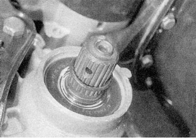
1. Clean and dry the grooves of the inner CV joint and the differential side gear shaft. Apply a small amount of molybdenum grease to them (Renault recommends Molykote BR2). Where necessary, install a new sealing ring onto the end of the pinion shaft and slide it along the shaft toward the transmission seal (refer to the accompanying illustration).
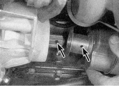
2. Place the drive shaft on the side gear shaft slots, aligning their holes for the cylindrical pins (refer to the accompanying illustration).
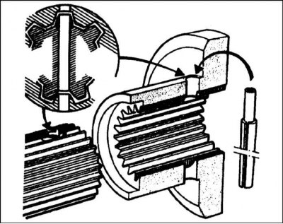
3a. Location of the cylindrical pin of the inner CV joint of the right drive shaft.
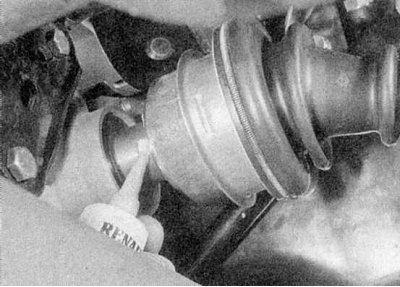
3b. Install new roll pins so that their grooves are 180° apart, then apply sealant to the ends of the pins (Renault recommends CAF 4/60 THIXO or Rhodoseal 5661) (refer to the illustrations).
4. Follow the steps described for LEFT DRIVE SHAFT - MODELS WITH MANUAL TRANSMISSION.
Both drive shafts - models with AD4 automatic transmission
1. Clean and dry the grooves of the inner CV joint and the differential side gear shaft. Apply a small amount of molybdenum grease to them (Renault recommends Molykote BR2).
2. Place the inner CV joint onto the grooves of the side gear shaft.
3. Follow the steps described for LEFT DRIVE SHAFT - MODELS WITH MANUAL TRANSMISSION.