
2. Using special pliers, remove the retaining ring that secures the tripod to the drive shaft. Please note that on some models the CV joint can be fixed with a blocking rim; in this case, detach the hinge using a file. Mark the position of the CV joint tripod on the drive shaft.
3. Remove the tripod. If this fails, use a puller. Make sure that the puller feet are behind the tripod and not touching the tripod rollers. Alternatively, a hydraulic press can be used.
4. The boot/bearing assembly is removed in the same way. Remove the fixing plate, remembering its correct position.
5. Get a protective cover equipped with a bearing.
6. Because the bearing is sealed with a sealing lip, a press must be used to install the boot/bearing assembly onto the drive shaft. The usual way (hammer and tubular punch) will inevitably damage the seal.
7. Install the mounting plate on the drive shaft, orienting it correctly.
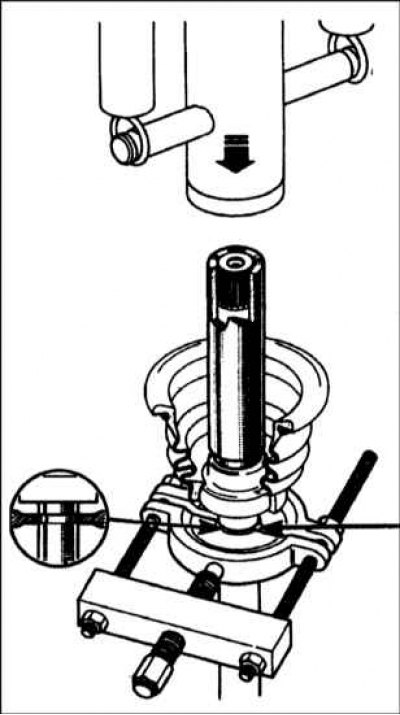
8a. Tighten the drive shaft and use a press to install the bearing/booth assembly onto it, using a hollow drift that should only rest against the inner race of the bearing.
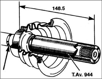
8b. Position the bearing so that the distance from its inner surface to the end of the drive shaft is 148.5 mm (refer to illustrations).
9. Align the marks made during removal and install the CV joint tripod on the grooves of the drive shaft. Use a hammer and a soft metal drift or a press.
10. Secure the tripod with the retaining ring (it should fit into the groove of the shaft). Where a circlip is not used, secure the end of the drive shaft with a hammer and punch by tapping on its edge at three equidistant points.
11. Install the drive shaft as described in Section Removal and installation of a power shaft.