
Removing
1. Remove the cap from the hub nut using a large screwdriver.
2. Loosen the hub nut with a socket head by 30 mm.
Attention! The wheel hub nut has a very high tightening torque. When unscrewing the nut, the car must be on wheels with the gear engaged and the parking brake applied.
In the workshops, the hub nut is unscrewed by lifting the car.
3. Remove the wheel brake caliper, see relevant chapter.
4. Cars with ABS. Unscrew the mounting bolt and remove the wheel speed sensor 3 (see illustration). To unscrew the sensor mounting bolt, you need a TORX T30 wrench.
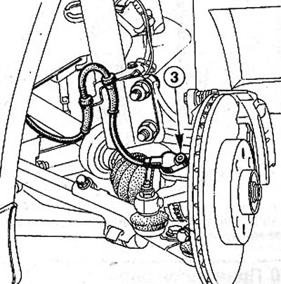
9.4 Unscrew the mounting bolt and remove the wheel speed sensor 3. Vehicles with ABS9.4 Unscrew the mounting bolt and remove the wheel speed sensor 3. Vehicles with ABS
5. Unscrew the two bolts securing the brake disc to the hub, using the TORX T40 key, and remove the brake disc (see illustration 9.4).
6. Unscrew the hub nut. In workshops, when unscrewing the nuts, they use the Rou device. 604-01 to prevent hub rotation (see illustration). This device can be made independently from strip iron.
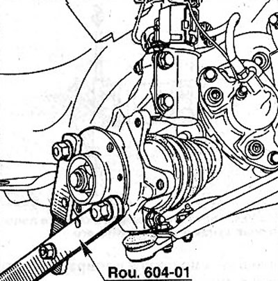
9.6 In workshops, when unscrewing the nut, use the tool Rou. 604-01 to prevent hub rotation
7. Press out a finger of a spherical support of a tip of cross steering draft from a rotary fist, the corresponding chapter see.
8. Disconnect the transverse lever from the steering knuckle by unscrewing the nut of the clamping bolt 2 fingers of the ball joint (see illustration). Remove the clamping bolt and press the transverse arm down.
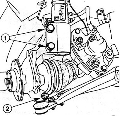
9.8 Disconnect the transverse arm from the steering knuckle by unscrewing the nut of the clamping bolt 2 of the ball joint pin
9. Unscrew the bolts 1 fastening the lower part of the shock absorber to the steering knuckle (see illustration 9.8).
10. Remove the hub from the driveshaft shank using a suitable puller, e.g. HAZET 787N (see illustration). Before doing this, secure the drive shaft with wire so that it does not fall after removing the hub. Otherwise, it may damage the CV joints.
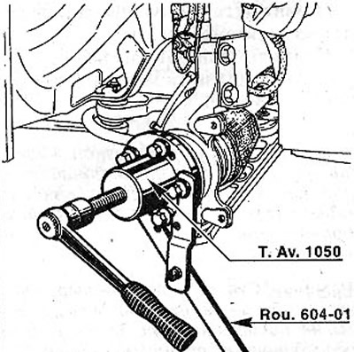
9.10 Remove the hub from the drive shaft shank using a suitable puller, e.g. HAZET 787N
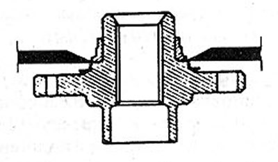
11. Press out hub 1 with a press (see illustration).
9.11 Press out hub 1 with a press
12. Remove the bearing inner race from the hub using a cam puller, e.g. HAZET 775 (see illustration).
9.12 Remove the bearing inner race from the hub using a cam puller, e.g. HAZET 775
13. Remove retaining ring A bearing from the groove on the hub (see illustration 9.18). To do this, you need needle-nosed pliers that compress the ring.
14. Press out the outer ring with both inner rings from the steering knuckle (see illustration). Bearing races and o-rings do not need to be removed before pressing out the outer ring.
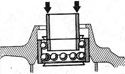
9.14 Press the outer ring with both inner rings out of the steering knuckle
Installation
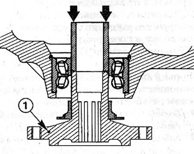
15. Establish the bearing in gathering in a rotary fist and press in it. Depending on the diameter of the bearing, a piece of pipe is used for this purpose, which is installed on the outer ring of the bearing (see illustration).
9.15 Install the bearing assembly into the steering knuckle and press it in
Attention! Do not support the press-in tube against the inner ring, as this will damage the bearing balls under the press-in pressure.
16. Remove the plastic sleeve (used for transportation and storage of the bearing) from a new bearing.
17. Lubricate the bearing surfaces with bearing grease (lithium grease).
18. Insert a new retaining ring A into the groove on the hub (see illustration).
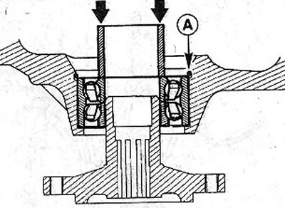
9.18 Insert the new circlip A into the groove on the hub
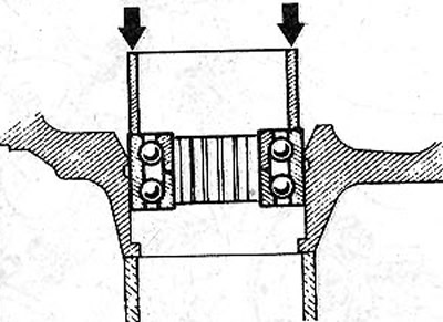
19. Connect a nave and a rotary fist. To do this, you need a piece of pipe, which must be supported on the inner ring of the bearing.
20. Apply LOCTITE SCEBLOC protective grease to the splines of the drive shaft shank, having previously cleaned and degreased them, for example, with a rag soaked in alcohol (see illustration).
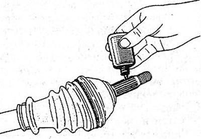
9.20 Apply LOCTITE SCEBLOC protective grease to the splines of the driveshaft shank, having previously cleaned and degreased them, for example, with a rag soaked in alcohol
21. Get the shank of the drive shaft into the hole of the hub and steering knuckle.
22. Thread a new hub nut onto the shank. Do not tighten the nut.
23. Fasten the transverse arm to the steering knuckle by connecting the ball joint, as well as the lower part of the shock absorber. At the same time, replace the nuts of the clamping bolt of the ball joint and the bolts of the suspension strut with new ones. Tightening torques for threaded connections:
- bolts for fastening the shock absorber to the steering knuckle-170 Nm;
- nut of a clamping bolt of a spherical support of the cross-section lever - 80 Nm.
Attention! Bolts of fastening of an amortization rack to a rotary fist establish in the direction from front to back that heads of bolts were turned in the direction of the car movement.
24. Reinstall the ball joint pin of the tie rod end, see the appropriate chapter.
25. Secure to the hub with socket head cap screws (TORX) and tighten them with 20 Nm.
26. Install the brake caliper, see the relevant chapter.
27. Install the ABSh sensor on the hub and tighten it.
28. Establish a wheel, being guided by marks made before removal and screw in wheel bolts.
29. Lower the vehicle onto the wheels and tighten the wheel bolts in a criss-cross pattern to 90 Nm.
30. Tighten the hub nut to 250 Nm.
Attention! At the same time, the car must be on wheels with the gear engaged and the parking brake applied.