



Contents: Removal 🠛 Installation 🠛
Caution! The bearing has a built-in signal disk for the wheel speed sensor, take measures to avoid damaging the disk (if there is one) when installing the bearing.
Removal
Remove the steering knuckle.
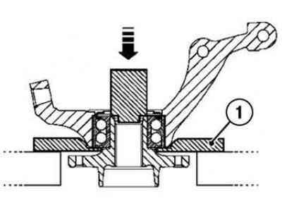
Fig. 4.18. Pressing the hub out of the bearing: 1 – puller
Using a press, press the hub out of the bearing, installing a mandrel with an outer diameter of 36.5 mm on it, and a puller under the steering knuckle (Fig. 4.18).
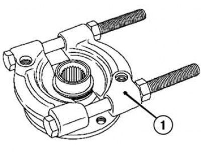
Fig. 4.19. Pressing out the inner bearing ring from the hub: 1 – puller
Original publication on the portal (RenaultBook)
Press the inner bearing ring out of the hub using a puller (Fig. 4.19).
Place the puller jaws into the groove of the inner ring of the hub bearing and remove it.
Remove the bearing retaining ring.
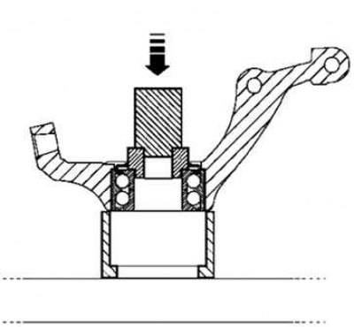
Fig. 4.20. Removing the outer bearing ring
Remove the outer bearing ring by resting a piece of pipe with an outer diameter of 65 mm against the inner ring (Fig. 4.20).
Caution: Do not use the sensor holder as a support (if it is installed).
Installation
Caution! Do not move the vehicle without the drive shafts installed in the wheel hubs and tightened to the required torque, as this may result in the destruction of the wheel hub bearings and damage to the ABS toothed signal disc.
Caution! Be sure to check the condition of the hub surface and the steering knuckle bore before installing the bearing. Replace the damaged steering knuckle.
Clean:
- the inner and outer surfaces of the new bearing that come into contact with the steering knuckle and the hub;
- surfaces of the steering knuckle in contact with the new bearing;
- hub surfaces in contact with the new bearing.
Install the sensor holder.
If the vehicle is equipped with a wheel speed sensor, position the sensor holder at an angle X 35° ±5° from the vertical axis of the steering knuckle: this position corresponds to the center of the seat (Fig. 4.21).
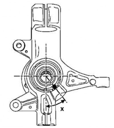
Fig. 4.21. Installing the wheel speed sensor holder
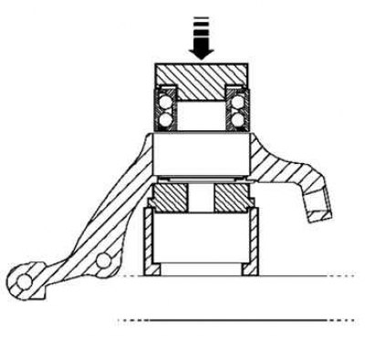
Fig. 4.22. Primary pressing of the bearing
To press the bearing, install a mandrel with an outside diameter of 70 mm on the outer ring (Fig. 4.22).
Caution! To avoid damaging the bearing, do not lean on the inner ring, as the bearing pressing force is very high.
Install the bearing retaining ring.
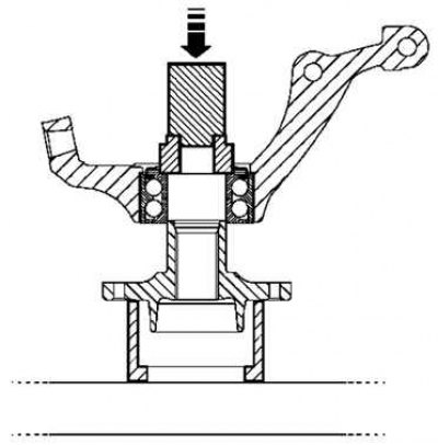
Fig. 4.23. Secondary pressing of the bearing
To press the bearing, install a mandrel with an outer diameter of 50 mm on the inner ring (Fig. 4.23).
Install the steering knuckle assembly with the hub and bearing onto the vehicle.
Tighten to the specified torque:
- suspension arm ball joint mounting bolt (62 Nm);
- tie rod end ball joint fastening nut (37 N·m);
- hub nut (280 Nm);
- shock absorber strut to steering knuckle mounting bolts (105 Nm);
- brake disc mounting screws (140 Nm);
- shoe guide mounting bolt (105 Nm);
- wheel mounting bolts (110 Nm).