
Removing
Place the car on a two post lift.
Unlock the steering wheel.
Remove the wheel from the corresponding side.
Disconnect the wheel speed sensor wire holder (if it is installed).
Remove the wheel speed sensor.
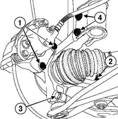
Pic. 4.15. Loosen the front brake shoe guide bolt: 1 - fitting for pumping; 2 – a nut of fastening of a finger of the spherical hinge; 3 – a bolt of fastening of a spherical support of the suspension arm; 4 – bolts of fastening of a shock-absorber rack to a rotary fist
Loosen the front brake shoe guide bolts (pic. 4.15).
Hang the bracket assembly with the front brake shoe guide from the suspension spring.
Remove:
- hub nut with tool (Rou. 604–01);
- brake disc mounting screws;
- brake disk;
- ball joint pin fastening nut;
- tie rod end;
- bolt of fastening of a spherical support of the suspension arm;
- bolts of fastening of a shock-absorber rack to a rotary fist (pic. 4.16).
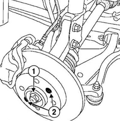
Pic. 4.16. Loosening the brake disc fixing screw: 1 – a nut of fastening of a nave; 2 – screws of fastening of a brake disk
Press out the ball joints using the tool (Tav. 476).
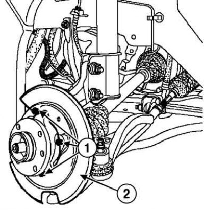
Pic. 4.17. Removing the front brake disc guard: 1 – a bolt of fastening of a casing; 2 – a protective casing of a disk of a forward brake
Loosen the bolt securing the front brake disc guard (if it is installed) and remove the disc guard (pic. 4.17).
Remove the steering knuckle.
Attention! Be careful not to damage the lower end of the shock absorber during operation.
Installation
Installation is made in an order, the return to removal.
Torque tighten:
- bolts of fastening of a shock-absorber rack to a rotary fist (105 Nm);
- ball joint bolts for suspension arms (62 Nm);
- nut of fastening of a finger of a ball joint of a tip of steering draft (37 Nm);
- brake disc screws (140 Nm);
- hub nut (280 Nm);
- guide rail mounting bolts (105 Nm);
- wheel bolts (110 Nm).
Attention! Press the brake pedal several times to set the pistons to the working position.
Adjust wheel alignment.