
2. Remove the suspension arm brace between the suspension arm and bracket from the stringer and disconnect the anti-roll bar support from the suspension arm (fastened with a nut),
3. Remove a nut of the top hinge and wring out a spherical finger from a rotary fist. To do this, use a ball pin puller. Remove the upper control arm pivot bolt nut (see illustration).
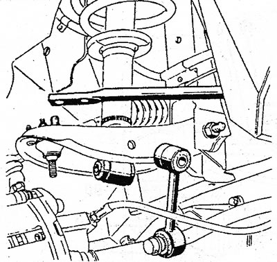
8.3 Partially dismantled front suspension. Upper suspension arm, shock absorber, arm extension and anti-roll bar linkage and arms already removed
4. Knock out the hinge bolts from the back of the shock absorber (where the other end of the anti-roll bar is attached).
5. Remove the nut from the inside of the cross member and knock out the hinge without damaging the threads. Jack up the control arm, simultaneously press down from the inside and remove the lower shock absorber mount.
6. Install the transverse suspension arm in; reverse sequence. Apply graphite grease to the pivot bolts and lower shock mounting bolts.
7. Install in sequence: upper control arm pivot bolt, shock absorber lower bolt, and anti-roll bar link.
8. Wrap all bolts and nuts with your fingers, and then tighten the following fasteners with a regulated tightening torque: fastening of the extension of the suspension arm to the transverse arm of the suspension, the lock nut on the lower end of the shock absorber and the nuts of the suspension ball joint. Tightening torques see illustrations 6.1 and 6.2.
9. Lower vehicle onto wheels and tighten all other connections to torque as described in chapter 7. Since it is quite difficult to get to all the bolts and nuts, drive the car onto a flyover or onto a repair frame.