
Removing
1. Remove from the car standing on wheels the clamps 1 of the stabilizer bar mounting, which are screwed to the transverse levers (see illustration) lower the stabilizer down. For models with a diesel vehicle with a turbocharger, the stabilizer bolt must be unscrewed from the upper side of the transverse arm.
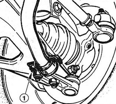
7.1 Remove the anti-roll bar clamps 1, which are screwed to the transverse levers, from the vehicle standing on wheels
2. Mark with paint the position of the front wheels on the hubs. This will allow the assembly to set the balanced wheel in its original position.
3. Loosen the wheel bolts. In this case, the car must be on the ground.
4. Stand in front of the car on the goats and remove the front wheels.
5. Unscrew the nut and remove the clamping bolt 1 of the ball joint pin (see illustration).
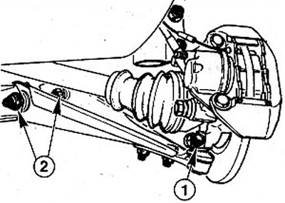
7.5 Unscrew the nut and remove the clamping bolt 1 of the ball joint pin
6. Pull the transverse arm down. This will release the ball joint pin from the hole in the steering knuckle. If the ball joint is too tight, use a pry bar to loosen it.
7. Unscrew the two bolts 2 securing the transverse arm to the support frame (see illustration 7.5).
8. Remove the transverse arm.
Silent blocks - check and replacement
9. Inspect the silent blocks of the transverse levers and make sure that the rubber of the silent blocks is not damaged or porous. If necessary, replace them with new ones.
Attention! In order for the alignment of the silent blocks not to change, remove and change them one by one.
10. Press out the damaged silent block using a small piece of pipe with an outer diameter of 44 mm (see illustration).
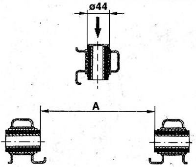
7.10 Press out the damaged silent block using a small piece of pipe with an outer diameter of 44 mm
11. Press in a new silent block using the same piece of pipe. In this case, the distance A should be 147±0.5 mm (see illustration 7.10).
12. Press in the second silent block. Distance A must also be 147±0.5 mm.
Installation
13. Bolt the transverse arm to the base frame of the attachments and screw the nuts 3 onto the bolts. Do not overtighten the nuts. Both nuts must face the direction of travel of the vehicle (see illustration).
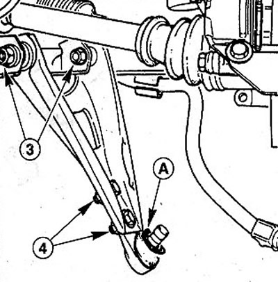
7.13 Both nuts must face the direction of travel of the vehicle
14. Make sure that there is a sealing plastic gasket A on the finger of the ball joint of the transverse lever (see illustration 7.13). Replace the gasket if necessary.
15. Get a finger of a spherical support in an aperture on a rotary fist. Insert the clamping bolt and secure it with a new nut using 80 Nm.
16. Reinstall the anti-roll bar and secure it. Do not final tighten the stabilizer mounting bolts.
17. Establish forward wheels according to the marks put at removal. Before doing this, lubricate the centering saddle of the rim on the hub, as well as the cone of the wheel bolts with a thin layer of bearing grease. Do not lubricate the threads of the wheel bolts.
18. Screw in wheel bolts and lower the car.
19. Tighten the wheel bolts in a cross pattern to 90 Nm.
20. Press the front of the car several times to sag and level the suspension.
21. Tighten the nuts 3 securing the transverse arm to the carrier frame (see illustration 7.13). The tightening torque of the nuts for 8CEIC vehicles is 100 Nm, for all other models it is 90 Nm.
22. Tighten the stabilizer bar mounting bolts. Tightening torques:
- SCENIC vehicles = 20 Nm;
- other models = 35 Nm.