
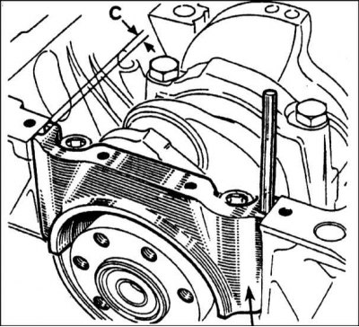
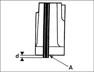
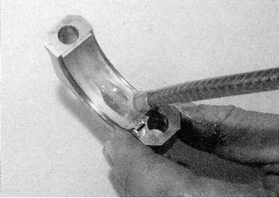
Insert a drill or pin of suitable diameter into the side seal groove (refer to accompanying illustration). This diameter will be the size of the side seal groove. If it is less than or equal to 5 mm, a 5.10 mm thick side seal must be used.
If the size is larger than 5mm, a 5.4mm thick side seal will be required. Please note that silicone sealant is only used in place of the side seals when the engine is assembled at the factory.
1. Clean the back side of the liners and the bearing surfaces of the liners in the cylinder block and in the covers.
2. Insert the inserts into the caps, making sure that the tab on the insert fits into the notch in the cap. Pay attention to the following paragraphs.
- a) On all engines except K7M, liners without lubrication holes are installed in the covers.
- b) On the K7M engine, in main bearing caps 2 and 4, liners with grooves are installed, and in caps 1, 3 and 5, liners without grooves (refer to accompanying illustration).
3a. Insert the liners into the seats in the cylinder block. Note the following paragraphs.
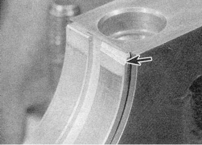
a) On all engines except K7M, liners with lubrication holes / grooves are installed in the block. On the E7J engine, the #5 upper main bearing is different from the others, it has an oil pump gear lubrication chamfer that must face the drive belt (refer to accompanying illustration).
- b) On the K7M engine, in main bearing caps 2 and 4, liners with grooves are installed, and in caps 1, 3 and 5, liners without grooves (refer to accompanying illustration).
- With) On all engines, if old liners are used, they must be installed in their places in the block and in the covers.
4. Before finally installing the crankshaft, check the operating clearance of the main bearings; this can be done in one of two ways. First method (internal micrometers or calipers required) - Establish covers of radical bearings on the block of cylinders with loose leaves in working situation. Tighten the cap bolts to the specified tightening torque and measure the diameter of the hole formed by each pair of bushings (bearing inner diameter). Measure the diameter of each crankshaft journal and subtract it from the inside diameter of the bearing. The result obtained is equal to the working clearance of the main bearing. Second (and more accurate) the method consists in using a special Plastigauge tool. The tool consists of a scale and plastic threads of round cross section. The procedure using Plastiquage is as follows.
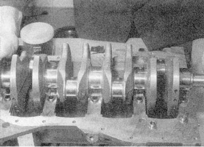
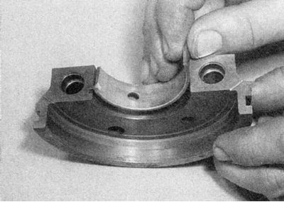
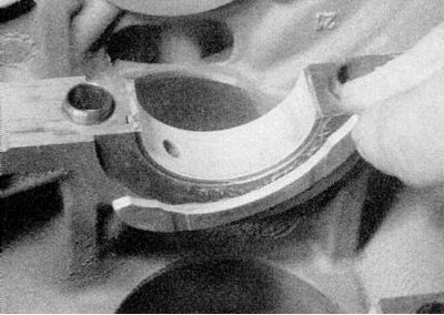
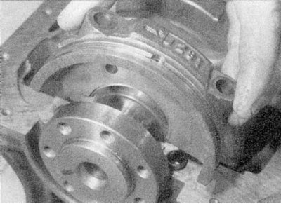
5. Install the upper main bearing shells in the working position and carefully lower the crankshaft into the crankcase (refer to accompanying illustration). Do not use any lubricant, the crankshaft journals and bearings must be absolutely clean and dry.
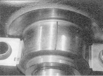
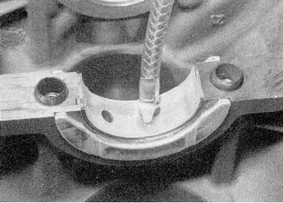
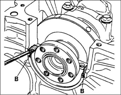
6. Cut a few pieces of Plastigauge thread to the right size (they should be slightly shorter than the width of the main bearings) and place a piece on each neck (refer to accompanying illustration).
7. Replace the covers with inserts. Be careful not to dislodge the Plastigauge.
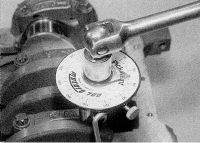
8. Starting from the central main bearing, tighten the main bearing cap bolts to the torque given in the Specifications and tighten to the angle specified in the Specifications (K7M engine). Do not rotate the crankshaft during this operation.
9. Turn out bolts and accurately remove covers of radical bearings.
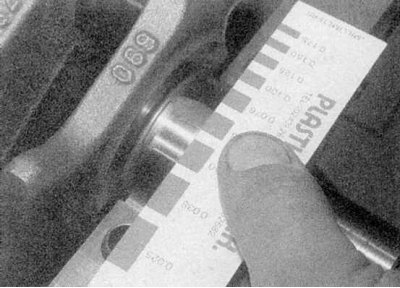
10. Compare the width of the deformed thread with the scale. The working clearance is indicated on the scale (refer to accompanying illustration). Compare the result obtained with the data given in the Specifications.
11. If the gap is too large, the wrong size bushings are installed or they are excessively worn (if old liners are reused). Before deciding that the crankshaft is worn, make sure that no dirt or oil has entered between the bearing shells and the caps or block when measuring the clearance. If one end of the Plastigauge is wider than the other, the crankshaft journal may be tapered.
12. Carefully clean all traces of Plastigauge from the crankshaft and liners.
Final installation
1. Carefully lift the crankshaft out of the cylinder block.
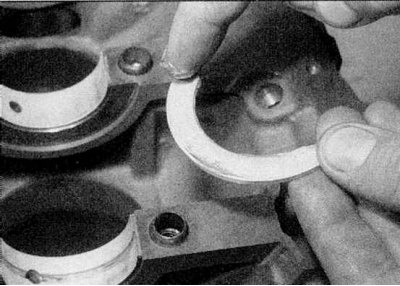
2a. Using a little grease, secure the thrust washers on each side of the center main bearing (E7J and K7M engines) or main bearing No. 2 (all other engines).
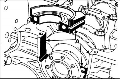
2b. The oil grooves on the thrust washers must face outward towards the crankshaft counterweights (refer to illustrations).
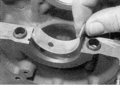
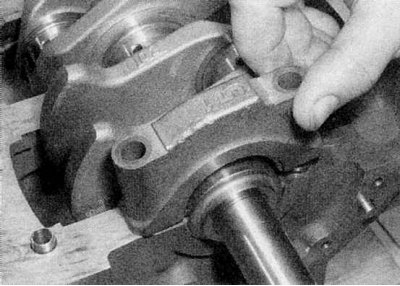
3. Liberally lubricate each liner in the cylinder block and lower the crankshaft into place (refer to accompanying illustration).
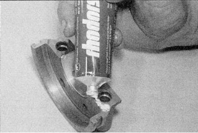
4a. Lubricate the bushings, then reinstall the bearing caps (refer to illustrations). Pay attention to the following paragraphs.
- a) On the E7J engine, apply a thin coat of sealant to the outer corners of the #1 main bearing cap.
- b) On a K7M engine, apply a thin layer of sealant to all contact surfaces of the No. 1 main bearing cap (refer to illustrations).
- With) When installing butyl seals, position them so that the grooves are facing outward at the bottom by approximately 0.2mm (to crankcase).
4d. Lubricate the seals and apply a small amount of sealant to the corners of the cover base.
4e. When installing the cover, use the bolts as guides, then firmly press the cover (refer to accompanying illustration).
- 4f. d) If silicone sealant is used when installing the No. 1 main bearing cap, do not press it in immediately, but leave it raised so that the first few threads of the main bearing bolts can only be entered.
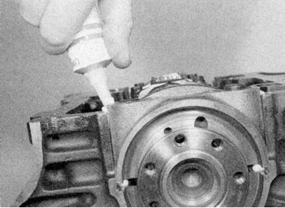
4g. Now inject sealant into each of the grooves on the side of the cover until it inserts into place below the cover and completely fills the grooves.
5a. Establish bolts of fastening of covers of radical bearings and tighten them gradually given in Specifications by effort.
5b. Tighten them to the specified angle on the K7M engine. (refer to illustrations).
6. Where butyl seals are installed, cut off protruding ends.
7. Where a silicone sealant is used to seal the cap, mix it with the hardener as described in the instructions. Pour the mixture into the grooves of the cover, completely filling them. Wait a few minutes, then cut off excess sealant from the connector surface, inside and outside of the cylinder block.
8. Check that the crankshaft rotates freely.
9. Check up an axial backlash of the crankshaft, address to Section Removal and installation of the oil pan (only for gasoline engines of the K7M series with an aluminum sump).
10. Install the new crankshaft oil seal from the toothed belt side into the casing, and then install the casing.
11. Install a new crankshaft oil seal on the flywheel/drive plate side.
12. Where applicable, install lower inner toothed belt cover.
13. Finally, install the piston/drive plate assemblies, oil pump and crankshaft sprocket, and finally install the new timing belt.