
MOT No. 45
Since the 16-valve engine is equipped with hydraulic lifters, it does not require valve clearance adjustment. In this case, in the Renault service plan, there is no work to check and adjust the clearance in the valve mechanism.
In the absence of a special wrench, when adjusting the clearance in the valve mechanism, a SW 10 wrench will be required (horn or cap) to loosen the lock nuts and pliers, but rather a suitable small wrench for adjusting the valves. In addition, you need, as shown in the figure for the intake valve of the 1st cylinder, a feeler gauge 0.15 mm thick (for adjusting the intake valve clearance) or 0.20 mm (to adjust the clearance in the exhaust valves).
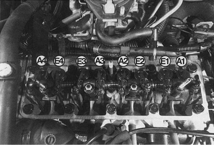
Due to the different clearance in the valve mechanism for the intake (E) and exhaust valve (A) at the engine type «WITH» during adjustment, be careful not to mix them up. To do this, we give the numbering of the cylinders with the designation of the valves.
Adjustment of the gap is provided only in the event of noise or after repair. We think that checking the clearance in the valve mechanism every 50,000-60,000 km is necessary for your car. On all types of Renault 19 engines, the clearance in the valve mechanism is adjusted on a cold engine.
Engine type «WITH»
The following tools are required: socket wrench SW 10, feeler gauge and one open-end wrench SW 10 each or a commercially available special wrench for adjusting the gap (lock nut wrench). You should also prepare a new gasket for the cylinder head cover, as it often breaks when the cover is removed. Often the old gasket will harden to the point where it no longer seals sufficiently the next time the cylinder head cover is installed.
1. Disconnect the battery ground wire from the terminal.
2. Remove the air filter, see section Air filter and inlets.
3. Disconnect, if necessary, the wire and hoses from the back of the block head cover and, for greater convenience, fasten with adhesive tape or cord to one side of the engine compartment.
4. Disconnect the throttle cable from the throttle shaft lever and remove the cylinder head cover support.
5. Remove the plug connection of the injection unit housing. To do this, press the fuse.
6. Using a socket wrench SW 10, remove the cylinder head cover (3 nuts). To avoid damaging the gasket, you must remove it very carefully. If necessary, tap the cylinder head cover with light strokes of the hammer handle.
7. Place small parts such as screws and washers in one place so that they cannot fall into the cylinder head.
8. Set to the TDC position of the 1st cylinder (Pay attention to the correct direction of rotation!).
9. If the engine in the belt pulley moves back and forth a little, then the valves of the 1st or 4th cylinders overlap, which means that both rocker arms or push rods move in the opposite direction.
10. If the valves of the 4th cylinder overlap, then you need to adjust the clearance on the 1st cylinder.
11. For control, the outlet valve must always be fully open, i.e. the rocker should be squeezed out by the pusher bar all the way down. Based on this, in accordance with the ignition order 1-3-4-2, the following installation scheme is obtained:
| Exhaust valve open (rocker is fully sunk) on cylinder no | Inlet valve to be adjust on cylinder no | Exhaust valve to be adjust on cylinder no |
1 3 4 2 | 3 4 2 1 | 4 |
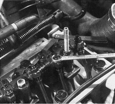
12. Measure the clearance in the valve train between the end of the valve stem and rocker arm. To do this, insert a wide feeler gauge between the valve stem and rocker arm. If the feeler gauge cannot be inserted, the clearance in the valve mechanism must be increased.
13. First of all, loosen the jam nut of the SW 10 tension bolt. At the same time, hold the adjusting bolt with a suitable wrench or pliers so that it does not rotate.
14. Turn the rocker arm adjusting bolt with pliers or a wrench until the appropriate feeler gauge fits the gap.
15. Tighten the lock nut and check the gap again, as when fixing with a lock nut, its value may change.
16. When adjusting the exhaust valves, make sure that the gap is not too small.
17. When adjusting the clearance on a 1.4-m type engine «WITH» when cold, the following values must be maintained: inlet valve 0.15 mm, exhaust valve 0.20 mm.
18. To open the next exhaust valve, turn the engine half a turn clockwise. For self-control, use the ignition distributor slider, which rotates 90° (right angle) in accordance with the ignition order 1-3-4-2.
19. Before installation of a cover of a head of the block of cylinders remove the rests of oil from a rag from a cover, laying of a cover and a head of the block of cylinders.
20. If the cover gasket is hardened and pressed through, it must be replaced.
21. Establish a cover of a head of the block of cylinders with a lining on a head of the block.
22. Install the nuts or bolts of the cylinder head cover and tighten them evenly.
23. Connect the throttle cable and adjust if necessary.
24. Install the air filter and connect the wire hoses.
25. Warm up the engine and check for oil leaks from under the cylinder head cover gasket.
Motor type «F» the valves are arranged in series in the cylinder head. Valve clearance is also measured with a feeler gauge. If the gap is larger or smaller than required, then the adjustment is carried out by replacing the existing shim with another with the required thickness. On this type of engine, a special tool is required to change the shims to adjust the valve clearance.
Engine type «F» (petrol and diesel)
On engines of the type «F» checking the clearances in the valve mechanism and adjusting them are carried out on a cold engine, however, this work on a power unit equipped with glass pushers is somewhat more complicated than on «C» -engine. You can easily check the gap yourself and determine if it needs to be adjusted.
Gap measurement
1. Remove the air filter.
2. Remove the top casing of a gear driving belt.
3. Unscrew cap nuts, covers of a head of the block of cylinders and carefully remove it. Be careful not to damage the cylinder head cover gasket.
4. If the cover is stuck, tap it with a hammer handle to make it easier to remove.
5. At the same time, the clearances in the intake and exhaust valves of the cylinder are measured. To do this, both valves must be unloaded.
6. Why turn the engine by moving the camshaft of the 1st cylinder (the first cylinder is located on the right in the direction of travel) will not be directed equally to the left and right upwards.
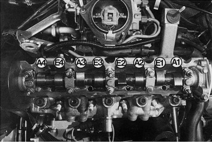
The designation of the valves is shown here so that you do not confuse the intake (E) and exhaust valves (A) F-motor when measuring valve clearance.
7. The clearance values in the valve mechanism are: for the inlet valve 0.20 mm and for the exhaust valve 0.40 mm.
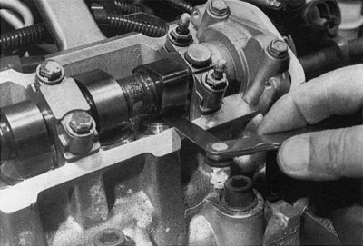
8. Check if the appropriate feeler gauge can be inserted between the camshaft and the pusher (e.g. for intake valve 0.20 mm).
9. If the gap has the required dimensions, then the probe should enter with some resistance.
10. If the feeler gauge does not pass, then check the gap with a feeler gauge that is 0.05 mm thinner.
11. Sometimes it happens that there is too much clearance; in this case, use a thicker feeler gauge to measure the clearance.
12. Write down the measurement results.
13. According to the ignition order (1—3—4—2) check the next cylinder, i.e. the third one.
14. To do this, turn the engine half a turn. Now for cylinder number 3, both cams should be directed equally to the left and right up. Now you can check the valve clearance of the 3rd cylinder.
Replacing shims
To check the valve clearance on the remaining cylinders, turn the engine half a turn for each successive cylinder (Nos. 4 and 2).
To adjust the valves from above, washers of various thicknesses are inserted into the glass pushers. Which washer to choose: thicker or thinner, depends on the size of the clearance in the valve mechanism. A special tool is required to replace the shims. With its help, the pushers are recessed and then the shims are removed.
When adjusting valves, a pressure device for valve lifters is used (Renault tool no. 992). You can also buy this device from companies that sell tools, for example, from MABECO, PO Box 130307, 42853 Remscheid. Adjusting washers can be purchased at stores selling spare parts for Renault.
1. The camshaft eccentrics of the adjustable cylinder should look up to the left and right (TDC). Rotate the crankshaft 1/4 turn clockwise. The piston is no longer at TDC. The valves do not come into contact with the piston.
2. To facilitate replacement of shims, turn both cup pushers of the adjustable cylinder until the groove points forward.
3. Install the pressing device between the cams of the adjustable cylinder, while both glass pushers are pressed at the same time.
4. Remove the shim using a thin screwdriver or pliers.
5. The adjusting plate must be labeled (indicating its size) down in the glass pusher.
6. If the washer is inserted incorrectly, its dimensions will not be visible. In this case, further adjustment can only be made using a micrometer in a car repair shop.
7. Calculate the required washer thickness.
8. Lubricate the new shim and insert with the stamped numbers down into the cup pusher.
9. Remove the clamping device and check the clearance in the valve mechanism.
10. Turn the engine and measure the clearance in the valves of the next cylinder.
What thickness to choose an adjusting washer?
When setting the gap, the adjusting washer for the exhaust valve must be selected due to the high temperature so that the gap is slightly larger than 0.40 mm, that is, the probe must enter freely. On the inlet valve, the gap is set exactly 0.20 mm. With a smaller gap than required, a thinner washer is used, with a larger one, respectively, a thicker one.
Measurement result | Adjustable parameter | Difference | Old adjusting plate | New adjustment plate | |
| Exhaust valve Inlet valve | 0.35 mm 0.25 mm | 0.40 mm 0.20 mm | -0.05 mm +0.05 mm | 3.85mm 3.70 mm | 3.80 mm 3.75mm |
A new engine usually uses medium thickness shims. In spare parts stores, shims with a thickness change of 0.05 mm from 3.25 to 4.50 mm are available. The thickness of the shims is etched into its bottom surface.
Note. Recommendation: To accurately measure the gap in the valve drive, it is best to insert the feeler gauge and not drag it through, since in this case the feeler gauge will get stuck if the gap is too small and thus «signal» about insufficient clearance.