
Note. This action is not included in the maintenance schedule. It should be done if noise is heard from the timing mechanism or if it is suspected that the loss of power is due to incorrect valve clearances. If installed incorrectly, a new valve cover gasket may be required.
1. If necessary, to improve access, release the hoses that run over the valve cover from the mount and move them to the side. If fuel lines are disconnected, plug open ends to prevent dirt from entering.
2. On models with the F8Q engine, unscrew the mounting bolts and remove the upper plastic cover of the drive belt / right engine mount, noting the location of the mounting bolts. On models with an F9Q engine, unscrew the fixing nuts and remove the soundproof cover.
3. Loosen the fixing nuts (F8Q engines) or bolts (F9Q engines) and remove the valve cover from the engine. Remove the gasket.
4. When carrying out the following procedure, the crankshaft must be turned with a wrench on the pulley bolt. To improve access to the bolt, jack up the front right corner of the vehicle and remove the wheel and wheel arch liner (attached with plastic clips).
5. To make it easier to turn the crankshaft, remove the glow plugs (Chapter Engine electrical equipment) or fuel injectors (Chapter Power and exhaust systems).
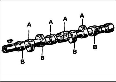
6. Draw the location of the valves on paper, numbering them from 1 to 8 from the flywheel (those. 1E, 2I, 3E, 4I, 5I, 6E, 7I, 8E; Where "E" is the exhaust valve "I" - inlet valve) (refer to accompanying illustration).
7. Rotate the crankshaft until the #1 cylinder valves are in an intermediate position - i.e. the exhaust valve will close and the intake valve will open. The piston of cylinder #4 will be at the top of the compression stroke and both of its valves will be completely closed - and now you can check the gaps of both valves of cylinder #4.
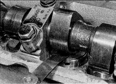
8. Insert the correct gauge (talk to Specifications) between the cam lobe and the washer on the top of the follower (refer to accompanying illustration). If the feeler gauge enters freely or does not enter at all, selecting feeler gauges of different thicknesses, determine the exact gap and write it down so that you can later calculate the required thickness of the new washer. Note that intake and exhaust valve clearances are different (talk to Specifications).
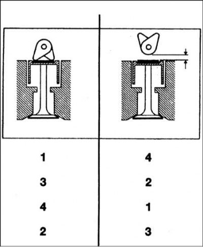
9. After checking the valve clearances of cylinder #4, turn the crankshaft half a turn so that the valves of cylinder #3 are in an intermediate position, then check the valve clearances of cylinder #2. Also check the clearances of the remaining valves in the sequence shown (refer to accompanying illustration).
F8Q engines
Note. A micrometer is required to make the adjustment.
Adjustment
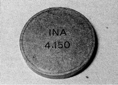
1a. Where the valve clearance differs from the regulated value, it is necessary to replace the adjusting washer, having previously calculated the desired thickness. Thickness is marked on the underside of the washer
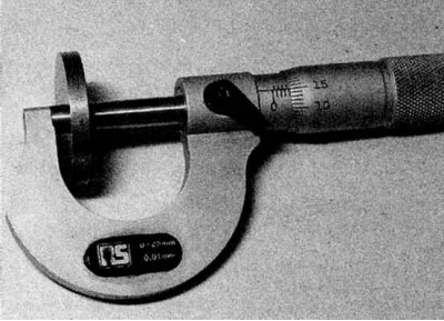
1b. But it is better to measure it with a micrometer, because due to wear, the washer may be thinner than indicated on it (refer to illustrations).
2. The required washer thickness is calculated as follows. If the measured clearance is less than the specified Specifications, subtract from the specified in Specifications clearance measured clearance, and then subtract this difference from the thickness of the existing washer.
For example:
- Calculation example - gap too small
- Measured clearance (A) = 0.15 mm
- Required clearance (IN) = 0.20 mm
- Difference (B-A) = 0.05 mm
- Installed washer thickness = 3.70 mm
- Required washer thickness = 3.70 - 0.05 = 3.65 mm
3. If the measured clearance is greater than the specified Specifications, subtract from the measured gap specified in Specifications gap and add the result to the thickness of the existing washer.
For example:
- Calculation example - clearance too large
- Measuring gap (A) = 0.50 mm
- desired clearance (IN) = 0.40 mm
- Difference (A-B) = 0.10 mm
- Installed washer thickness = 3.45 mm
- Required washer thickness = 3.45 + 0.10 = 3.55 mm
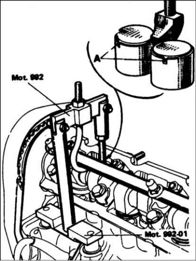
4. The washer can be removed from the tappet without removing the camshaft if a Renault special tool is available (refer to accompanying illustration).
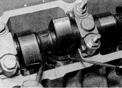
5. To remove the washer, the pusher must be pressed against the pressure of the valve spring. Theoretically, this can be done by resting the lever against the camshaft between the working surfaces of the cams with a suitable screwdriver, pressing the pusher with the shim down, but this is not recommended by the manufacturer. If you do use this method, be very careful not to damage the camshaft, cylinder head or tappet (refer to accompanying illustration).
6. When the pusher is pressed, the working protrusions of the cams should be directed upwards, and the pushers themselves should be turned so that their notches are perpendicular to the camshaft axis. Install the washer with the thickness marking facing down.
7. If a Renault tool is not available and a suitable replacement cannot be made, the camshaft will need to be removed to remove the washers as described in Section Removal, inspection and installation of the camshaft and pushers.
8. Remove socket or wrench from crankshaft pulley bolt.
9. Install the valve cover using a new gasket and tighten the mounting nuts to Specifications effort.
10. Install fuel injectors (as described in chapter Power and exhaust systems) or glow plugs (Chapter Engine electrical equipment).
11. Install/connect hoses that have been offset to gain access. If the fuel lines have been disconnected, connect them, and then bleed the fuel system as described in Chapter Power and exhaust systems.
12. Install the top plastic drive belt/right engine mount cover.
F9Q engines
Note. A micrometer is required to make the adjustment.
Adjustment
1. Where the valve clearance differs from the regulated value, it is necessary to replace the shim, having previously calculated the desired thickness. The thickness is indicated on the underside of the washer, but it is best to measure it with a micrometer and then calculate the new thickness as described for F8Q ENGINES above.
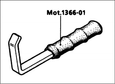
2. The adjusting washers are seated in the tappets so that they are very difficult to remove with the camshaft installed. To perform this procedure, you will need a special Renault tool (refer to accompanying illustration), but first you will need to remove the intake pipe and exhaust manifold and turbocharger (contact the head Power and exhaust systems).
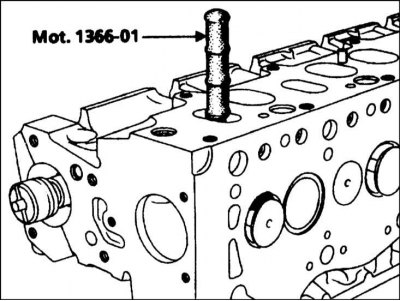
3. To remove the shim, turn the crankshaft in the normal direction until the adjustable valve is fully open. Insert the tool through the valve in the cylinder head so that the tip of the tool rests on the valve seat (refer to accompanying illustration).
4. When removing the inlet valve washer, rotate the crankshaft further 180°and reinstall the tool. The tool will hold the valve in the open position, allowing enough clearance to remove the washer with a screwdriver. Use the same procedure for the exhaust valves, except that the crankshaft must rotate 180°against the normal direction of rotation.
5. Before installing the washer, wipe the top of the pushrod and make sure all oil is removed from the washer recess in the top of the pushrod. Install the washer in the pusher, the protrusion should be located in the recess of the pusher.
6. If a Renault tool is not available, the camshaft must be removed to replace the washers as described in Section 8.
7. Remove the wrench from the crankshaft pulley bolt.
8. Install the valve cover using a new gasket and tighten the mounting bolts as shown in Specifications effort.
9. Install fuel injectors (as described in chapter Power and exhaust systems), or glow plugs (Chapter Engine electrical equipment).
10. Establish the inlet pipeline and a final collector and a turbocharger as it is described in the Head Power and exhaust systems.
11. Install/connect hoses that have been offset to gain access. If the fuel lines have been disconnected, connect them, and then bleed the fuel system as described in Chapter Power and exhaust systems.
12. Install the engine soundproof cover.