
Attention! These dowel pins are for the ONLY purpose of checking crankshaft position when performing various engine overhaul procedures. DO NOT use them as locking tools to hold the crankshaft stationary while loosening or tightening the pulley or flywheel/drive plate bolts.
1. TDC is the highest point in the cylinder that the piston reaches when the crankshaft rotates. Each piston is at TDC at the end of the compression stroke and also at the end of the exhaust stroke. However, to adjust the ignition timing, the TDC at the end of the compression stroke is taken into account. Cylinder #1 is located at the end of the engine facing the transmission.
2. When #1 piston is at TDC, the timing mark on the camshaft sprocket must be aligned with the pointer on the outer timing belt cover (the mark on the pulley can be seen through the slot in the cover, below the pointer). Additionally, the alignment mark on the flywheel must be aligned with the TDC mark on the clutch housing.
3. To align the alignment marks, it is necessary to rotate the crankshaft. This can be done with a wrench on the crankshaft pulley bolt. To improve access to the pulley bolt, jack up the front right corner of the vehicle, remove the wheel and remove the wheel arch liner (attached with plastic clips). To make the crankshaft turn easier, remove the glow plugs (Chapter Engine electrical equipment) or fuel injectors (Chapter Power and exhaust systems).
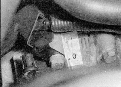
4. Looking into the opening in the clutch housing, turn the crankshaft so that the alignment mark on the flywheel is aligned with the TDC mark (0°) on the clutch housing (refer to accompanying illustration).
5. On models with the F8Q engine, unscrew the three mounting bolts and remove the top plastic drive belt/right engine mount cover from the top bracket, marking the location of the mounting bolts. On models with an F9Q engine, unscrew the fixing nuts and remove the soundproof cover.
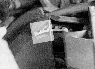
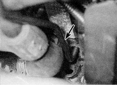
6. Make sure the timing mark on the camshaft sprocket is aligned with the pointer on the outside of the drive belt cover (refer to accompanying illustration). Piston #1 is now at TDC on the compression stroke.
7. You can check the position of the crankshaft as follows. If necessary, remove the air filter housing assembly (Chapter Power and exhaust systems).
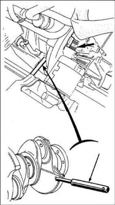
8a. The exact position of the crankshaft can be checked by inserting the dowel pin - tool Renault Mot. 861 (early version) or Mot/1054 (latest version).
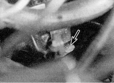
8b. To do this, unscrew the plug from the front left end of the cylinder block, near the base of the dipstick tube.
8b. Insert the dowel pin so that it fits into the groove in the crankshaft. It may be necessary to turn the crankshaft slightly forward or backward (refer to accompanying illustration).
Note. Do not attempt to rotate the motor with the pin installed. If the engine must be left in this condition for a long time, it is recommended to leave a warning note in the engine compartment.
9. Finally, remove the dowel pin and install all removed components.