



Elements of drive shafts
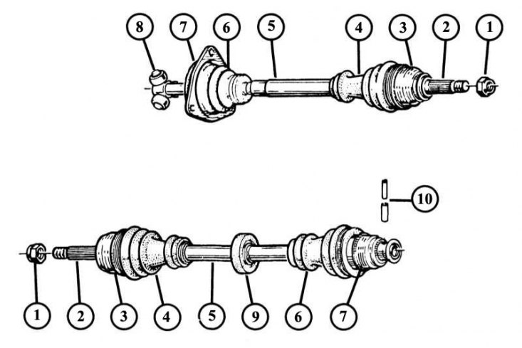
1 - wheel hub nut; 2 - end journal of the shaft from the wheel side; 3 - hinge shell; 4 - sealing cuff of the joint on the wheel side; 5 - drive shaft; 6 - sealing cuff of the joint on the wheel side; 7 - hinge shell; 8 - joint star; 9 - damper unit; 10 - expansion pins.
The picture shows the RC 490 joint (A and C) located on the gearbox side, and the GE76 / GE86 joint (B) located on the wheel side.
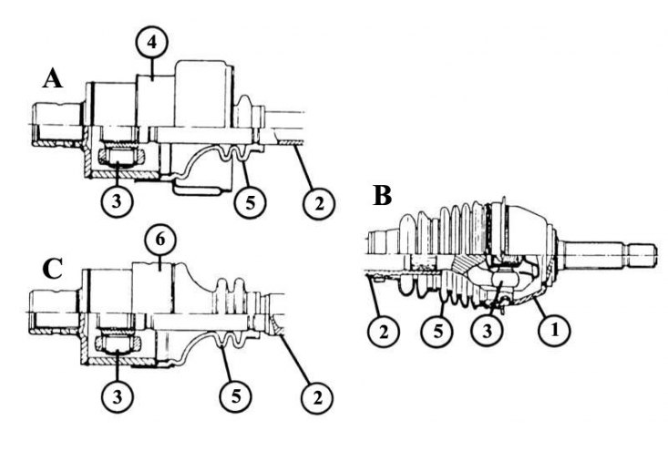
1 - hinge shell with axle neck; 2 - drive shaft; 3 - articulated sprocket; 4 - thermal insulation ring or steel sealing cuff; 5 - hinge sealing cuff.
The original can be found on the website: RENAULTBOOK
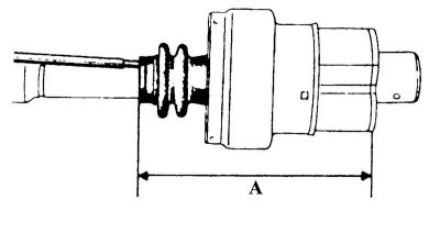
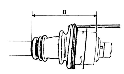
By means of stretching or, respectively, compression, the following interval between the end of the sealing cuff and the end face of the hinge must be established for the individual hinges:
- A - 155.5-157.5 mm (rC 490 joint);
- B - 152.5-154.5 mm (joint Gl 62).
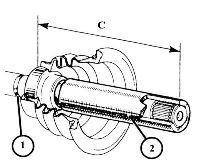
On the Gl 69 joint, there must be a distance of 148.5 mm between the sealing lip - ball bearing connection and the end of the shaft (C). The ball bearing equipped with a sealing ring may only be compressed using a suitable tube (2). To do this, use the groove (1) as a support for securing with suitable vice jaws, to avoid damaging the joint.
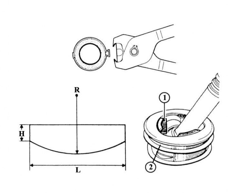
The figure shows special pliers used to tighten the band clamp by creating a loop on it.
Left: Shown here is a support with which the edge of the sealing sleeve limiting plate is bent on a Gl-62 type joint using a bronze mandrel. The support thickness should be 2.5 mm. Further measurements:
- R — radius 45 mm;
- H — height 6 mm;
- L — length 40 mm.
Right: After the limit plate (1) has been set to the required position, the support is removed from the hinge shell (2).
Depending on the type of engine installed on your Renault 19, the dimensions of the axle shafts are slightly different, but they have the same operating principle. The drive shaft joints are protected by rubber cuffs from moisture and dirt, and on the wheel side they are filled with a precisely calculated amount (joint GE 76 = 180 g; GE 86 = 295 g) high-quality lithium grease with molybdenum disulfide (Renault recommendations = MOBIL CVJ 825, MOBIL EXF 570 or Black Star). On the gearbox side, the joints are filled with a lubricant of the same specification (Gl 62 joint = 130 g; RC 490 = 160 g). The corresponding amount of grease is included in the repair kit.
1. Raise the car from the front and secure it so that the front wheels hang freely.
2. Spin each wheel by hand and check both sealing lips of the corresponding shaft for small cracks and brittle spots.
3. Are the tension band clamps securely fastened?
4. Traces of grease on the sealing cuff are a danger signal, since insufficient lubrication or dirt or moisture that gets inside will very quickly destroy the joint.
5. Replace damaged sealing cuffs immediately. To do this, the drive shaft must be disconnected from the corresponding drive joint.
Replacing the drive joint sealing cuff
Wheel side
1. Remove the drive shaft.
2. Remove the drive shaft seal from the gearbox side.
3. Tighten the shaft with the butt of the shaft axle located on the wheel side in a vice with protective jaws.
4. Carefully cut off the clamping straps using a knife or hacksaw for metal. Make sure that the groove of the hinge shell is not damaged.
5. Using nippers or a knife, cut the damaged hinge seal.
6. Remove the old layer of grease and check if it contains any dirt particles.
7. If the old grease contains a lot of dirt, clean the joint thoroughly (do not use any solvents) and check the degree of its wear. Replace the hinge if necessary.
8. Apply the grease supplied with the repair kit to the hinge shell and to the hinge.
9. Put on the new sealing cuff and make sure that the rubber bevels sit correctly in the grooves of the axle shaft and the hinge shell.
10. Squeeze the sealing cuff a little with your hands and move the joint to distribute the grease evenly.
11. Squeeze the sealing cuff and lift the edge of the cuff - this will remove excess air. The sealing cuff is now installed correctly.
12. Install new tension band clamps.
13. Using nippers - in a car repair shop, special pliers are used for this - make a loop again as described above and finally tighten the clamps.
14. Carry out further work as described for dismantling.
15. Remove the drive shaft.
Replacing the drive shaft seal
Gearbox side
1. Hinge type RC 490: use a pipe or pliers to press out 3 bends on the sealing cuff from sheet steel and turn the thermal insulation ring (depending on the version) using a hammer and punch downwards towards the hinge sealing cuff.
2. Joint type Gl 62: use a screwdriver to separate the spring ring from the hinge shell.
3. Both types of hinges: separate the rubber retaining ring from the drive shaft using nippers.
4. Use nippers or a knife to cut the damaged sealing cuff.
5. Hinge type RC 490: remove the hinge shell.
6. Joint type Gl 62: using a gas wrench, bend back the safety plate and remove the hinge shell.
7. Make sure that the rollers do not slip out of the bearing journals. All parts (rollers, bearings and needles) are fitted and ground to each other, so they cannot be swapped. To secure the parts, the hinge must be wrapped with adhesive tape.
8. Both types of joints: remove old grease and check for dirt.
9. If the old grease is contaminated, clean the joint (do not use solvents for this) and determine the degree of wear. Replace the joint if necessary.
10. Remove the thrust ring, if present, using pliers and press out the drive shaft joint.
11. When assembling, place the sealing cuff with the rubber thrust ring on the drive shaft. The applied grease will make it easier to put on.
12. Hinge type RC 490: depending on the design of the hinge, put on a sealing cuff made of sheet steel or a heat-insulating ring with a thrust metal ring.
13. Both types of joints: Insert the joint into the gear engagement of the drive shaft and press it onto the shaft.
14. Put on the retaining ring, if any, or secure the joint with 3 punch blows (every 120°).
15. Distribute the required amount of grease over the sealing cuff.
16. Hinge type RC 490: place the lubricated shell on the hinge.
17. Insert the hinge sealing collar with the thrust metal ring into the sheet steel collar or into the thermal insulation ring (depending on the design).
18. Place the sheet steel sealing cuff or, respectively, the thermal insulation ring until it stops on the hinge shell and make 3 packings for fixing on the steel cuff using a rounded mandrel.
19. Connect the hinge elements so that the distance between the beginning of the sealing cuff and the end surface of the hinge shell is from 155 to 157 mm.
20. To equalize the air pressure on the installed rubber cuff, carefully lift it off the drive shaft with a screwdriver.
21. Install the tension band clamp onto the drive shaft and tighten it by squeezing or making a loop using nippers or special pliers.
22. Joint type Gl 62: move the adjacent plate.
23. Slide the mating plate between the hinge shell and the safety plate.
24. Using a mandrel, bend the safety plate along the adjacent plate.
25. Remove the adjoining plate.
26. Slide the joint sealing cuff into the grooves of the drive shaft and the joint shell.
27. Connect the hinge elements so that the distance between the beginning of the sealing cuff and the end surface of the hinge shell is from 152.5 to 154.5 mm.
28. To equalize the air pressure on the installed rubber cuff, carefully lift it off the drive shaft with a screwdriver.
29. Secure the hinge seal with a spring ring and rubber rings.
30. Perform subsequent work in accordance with the disassembly description.