
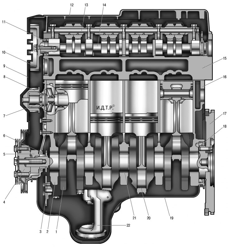
5.1. Engine (lengthwise cut): 1 - crankshaft; 2 – a cover of the main bearing of a cranked shaft; 3 – an asterisk of the oil pump; 4 – a pulley of a drive of auxiliary units; 5 – a gear pulley of a cranked shaft; 6 – a forward epiploon of a cranked shaft; 7 - water pump; 8 - toothed pulley of the water pump; 9 – a cover of a belt of a drive of the gas-distributing mechanism; 10 – a gear pulley of a camshaft; 11 – an epiploon of a camshaft; 12 – a cover of a head of the block of cylinders; 13 - the axis of the rocker arms of the valve drive; 14 - camshaft; 15 – a head of the block of cylinders; 16 - cylinder block; 17 - flywheel; 18 – a back epiploon of a cranked shaft; 19 - oil sump; 20 - connecting rod bearing shell; 21 – insert of the main bearing; 22 - inlet pipe of the oil pump
Both engines with in-line vertical arrangement of cylinders and liquid cooling have almost completely the same design, but differ in displacement. Moreover, the working volume of the K7M 710 engine is increased compared to the K7J 710 engine due to an increase in the piston stroke, which is achieved due to an increase in the crankshaft crank radius with the same cylinder diameter. This entailed an increase in the height of the cylinder block, which is different for these engines. In addition, due to the increased diameter of the clutch aggregated with the K7M 710 engine, the diameter of the flywheel is also increased, which entailed a change in the shape of the clutch housing of the gearbox. Therefore, the location of the threaded holes for attaching the gearbox to the cylinder blocks of these engines is also different. The device of engines is shown in fig. 5.1 and 5.2.
Engines with an overhead arrangement of one five-way camshaft have two valves per cylinder. The camshafts of both engines are driven by reinforced toothed belts. Engine valves are driven from the camshaft using rocker arms, resting on one shoulder on the camshaft cams and having bolts on the other shoulder to adjust the clearances in the valve mechanism with locknuts acting on the ends of the valve stems.
Cylinder heads 15 (see fig. 5.1) both engines are made of aluminum alloy according to the transverse cylinder scavenging pattern (inlet and outlet ports are located on opposite sides of the head). Seats and guide bushings are pressed into the heads 15 (see fig. 5.2) valves. The inlet 7 and outlet 16 valves each have one spring 14 fixed through the plate 13 with two crackers.
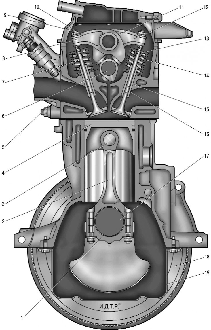
5.2. Engine (cross section): 1 – connecting rod cover; 2 - connecting rod; 3 - piston pin; 4 - piston; 5 - inlet pipe; 6 - camshaft; 7 - inlet valve; 8 - inlet valve rocker; 9 - adjusting bolt; 10 - locknut of the adjusting bolt; 11 - the axis of the rocker arms of the valve drive; 12 - exhaust valve rocker; 13 - valve spring plate; 14 - valve spring; 15 - valve guide sleeve; 16 - exhaust valve; 17 - crankshaft; 18 - flywheel; 19 - oil sump
On the upper plane of the head of the block, the axis 11 of the rocker arms 8 and 12, respectively, of the intake and exhaust valves, is bolted. In the holes in the shoulders of the rocker arms, bolts 9 locked with locknuts 10 are installed to adjust the gaps in the valve drive mechanism, based on the ends of the valve stems.
Camshaft 14 (see fig. 5.1) installed in the bed of bearings, made in the body of the head, and fixed from axial movement by a thrust flange.
The separation plane of the head and cylinder block is sealed with a gasket, which is a plate molded from sheet metal.
Cylinder blocks 16 (see fig. 5.1) Both engines are a single casting that forms the cylinders, the cooling jacket, the upper part of the crankcase and five crankshaft bearings made in the form of crankcase partitions. The blocks are made of special ductile iron with cylinders bored directly into the body of the block. The 2 main bearing caps are machined complete with blocks and are not interchangeable. Cylinder blocks have special lugs, flanges and holes for attaching parts, components and assemblies, as well as channels of the main oil line.
The crankshaft 1 rotates in main bearings having thin-walled steel liners 20 and 21 with an anti-friction layer. The axial movement of the crankshaft is limited by two half rings installed in the grooves of the bed of the middle main bearing.
Flywheel 17, cast iron, mounted on the rear end of the crankshaft and secured with six bolts. A gear rim is pressed onto the flywheel for starting the engine with a starter. In addition to it, a ring gear is made on the flywheel, which ensures the operation of the top dead center sensor of the engine management system.
Pistons (pic. 5.3) made of aluminum alloy. On the cylindrical surface of the piston head there are annular grooves for the oil scraper and two compression rings.
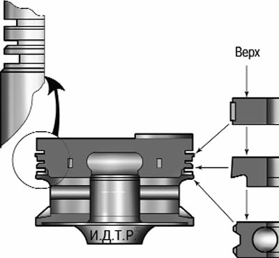
5.3. Piston and piston rings
Piston pins 3 (see fig. 5.2) installed in the piston bosses with a gap and pressed with an interference fit into the upper heads of the connecting rods, which are connected by their lower heads to the connecting rod journals of the crankshaft through thin-walled liners, similar in design to the main ones.
Connecting rods 2 steel, forged, with an I-section rod.
Combined lubrication system (see more details. «Engine lubrication system»).
The closed crankcase ventilation system does not communicate directly with the atmosphere, therefore, simultaneously with the exhaust of gases, a vacuum is formed in the crankcase under all engine operating modes, which increases the reliability of various engine seals and reduces the emission of toxic substances into the atmosphere.
The system consists of two branches, large and small.
When the engine is idling and under low load conditions, when the vacuum in the intake pipe is large, crankcase gases are sucked in by the intake pipe along the small branch of the system.
In full load modes, when the throttle valve is open at a large angle, the vacuum in the intake pipe decreases, and in the air supply hose it increases, and crankcase gases through the large branch hose connected to the fitting on the head cover, mainly enter the air supply hose, and then through the throttle assembly into the intake pipe and engine cylinders.
The engine cooling system is sealed, with an expansion tank, consists of a cooling jacket made in casting and surrounding the cylinders in the block, combustion chambers and gas channels in the cylinder head. Forced circulation of the coolant is provided by a centrifugal water pump 7 (see fig. 5.1) driven by a crankshaft timing belt. To maintain the normal operating temperature of the coolant, a thermostat is installed in the cooling system, which closes a large circle of the system when the engine is cold and the coolant temperature is low.
The power supply system of both engines consists of an electric fuel pump installed in the fuel tank, a throttle assembly, a fine fuel filter installed on the fuel tank, a fuel pressure regulator installed in the fuel pump module, injectors and fuel lines, and also includes an air filter.
The ignition system of both engines is microprocessor-based and consists of an ignition module, high-voltage wires and spark plugs. The ignition module is controlled by the electronic control unit of the engine management system. The ignition system during operation does not require maintenance and adjustment.
power unit (engine with gearbox, clutch and final drive) mounted on three supports with elastic rubber elements - two upper side (right and left), which perceive the bulk of the power unit, and the rear, which compensates for the torque from the transmission and the load that occurs when the car starts off, accelerates and brakes.
Note. This section describes engine repair work available to a novice master, such as replacing seals, power unit suspension mounts, checking compression, adjusting and lapping valves, etc. For the overhaul of the engine with its complete disassembly, special equipment and tools are required, as well as the appropriate technical training of the performer. Therefore, if such repairs are necessary, contact an authorized service station.