
Single point injection system
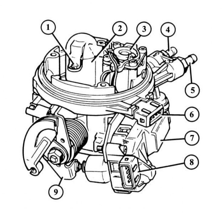
1 - intake air temperature sensor; 2 - nozzle receiver; 3 - fuel pressure regulator; 4 - fuel return fitting; 5 - fuel supply fitting; 6 - block connectors for the injector and intake air temperature sensor; 7 - throttle position regulator; 8 - block connectors of the throttle position regulator; 9 - throttle shaft lever.
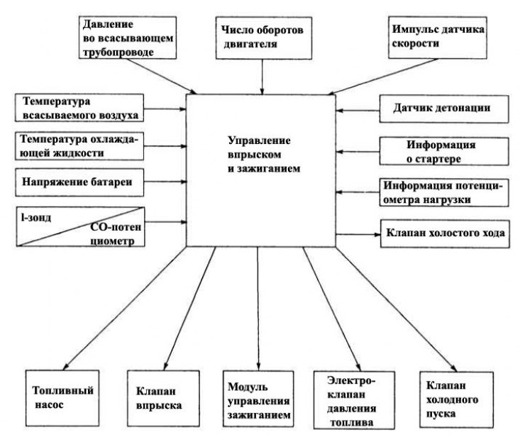
The operation diagram of a single point injection system shows the number of input signals that the control device converts into certain output signals. The diagram also explains the whole complexity of the system: even one faulty sensor can adversely affect the engine with incorrect input signals coming from it!
Bendix single point injection system with air filter removed
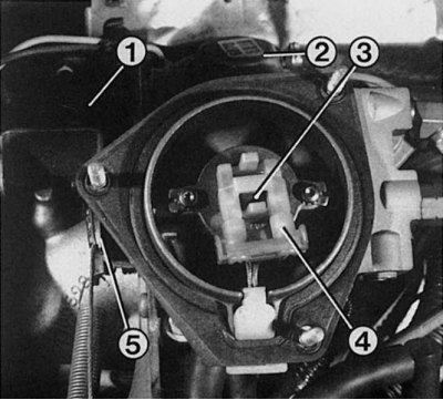
1 - throttle position regulator; 2 - EGR valve for exhaust gas return; 3 - nozzle with fastening; 4 - contact connection of the nozzle; 5 - throttle shaft lever with cable.
Her device
Renault 19 with 1.4-litre and some 1.7-litre and 1.8-litre engines are equipped with an integrated variable catalyst (triple acting catalyst) single point injection system.
The most important components and elements of a single-point gasoline injection system
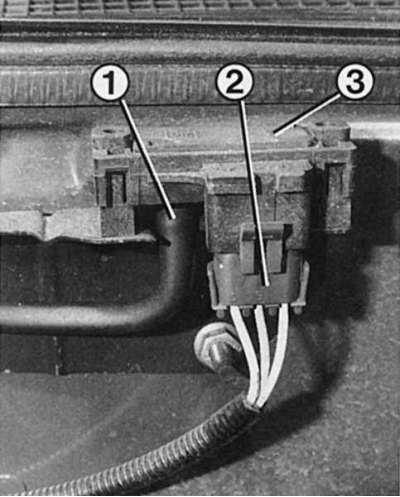
The electronic control device is placed on a bracket with a rubber expander in the right inner surface of the wing. Through the block connectors, the device is connected to the following elements of the injection system:
- The crankshaft flywheel speed sensor also serves to determine the TDC position of cylinder No. 1.
- Throttle Potentiometer (on Bosch throttle body) serves to determine the position of the throttle valve and the amount of intake air.
- The pressure sensor is designed to register the vacuum pressure in the intake manifold.
- The lambda probe is located in the catalyst inlet pipe and serves to determine the residual oxygen content in the exhaust gas.
- EGR valve (on the Bendix throttle body) on the intake manifold to reduce the amount of nitrogen oxides (NO3) in the exhaust gas.
- The idle switch is required to determine the position of the throttle - it is rigidly connected to the throttle servomotor.
- The full load switch serves (on the Bendix throttle body) to enrich the working mixture at wide open throttle.
- The knock sensor is located in the engine housing and serves to determine «detonation» combustion, see also chapter Ignition system.
- intake air temperature sensor (Bosch) installed at the inlet of the throttle body and serves to determine the temperature of the intake air and, accordingly, in the intake manifold (Bendix), as well as to determine the temperature of the working mixture.
- The engine temperature sensor is installed in the cooling system near the intake manifold (engine type «F») or in the intake manifold (engine type «C»).
- Based on the signals from this sensor, the control device calculates the opening time of the electromagnetically actuated injector and determines the amount of fuel to be injected. In this case, the control device is regulated by the so-called universal characteristic of the engine - a file in which data is collected about all possible states of the engine. Similarly, in this universal characteristic of the engine, the amount of injected fuel is determined depending on the incoming electrical signals. Additionally, for a single-point injection system, the data necessary for operation on the amount of fuel and the ignition moment have been entered into the universal characteristic of the engine.
Throttle valve
The throttle valve is located in the injection system housing below the nozzle directly in front of the intake manifold and is connected by a rod to the gas pedal. It doses the flow of intake air in modes from idle to full «gas».
Throttle Potentiometer
Elements of the Bosch injection system
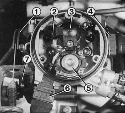
1 - throttle shaft lever with cable; 2 - intake air temperature sensor; 3 - casing with nozzle contact connection; 4 - contact connection of the potentiometer; 5 - fuel pressure regulator; 6 - block connector of the injector and intake air temperature sensor; 7 - throttle position regulator.
It informs the control device about the movement of the throttle valve and its position. A closed throttle activates the idle speed control process; throttle position regulator - its full opening, that is, the maximum enrichment of the working mixture. Rapid throttle opening feels like acceleration. If you take your foot off the gas pedal, the throttle close signal cuts off the fuel supply. Signal transmission is carried out by means of electricity, that is, the potentiometer is a conventional variable resistance.
Full load switch
Only for Bendix injection system
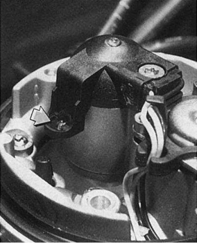
in the Bendix injection system, an exhaust gas recirculation valve is screwed into the muffler exhaust manifold (1). Diaphragm controlled by the control unit opens the valve by means of a solenoid valve and vacuum pipe (2). In this case, unburned exhaust gases enter the combustion chamber.
This switch is mounted on the mount along with the idle throttle control element. When the accelerator pedal is fully depressed, the throttle shaft lever actuates a microswitch, as a result of which the control device activates rich mixture at wide open throttle. In this case, the working mixture, depending on the amount of intake air at full throttle opening, will become more enriched.
Throttle position controller
A small electric motor with a worm gear pushes the pushrod onto the throttle levers. The purpose of the regulator is to adjust the throttle position at idle so that the engine runs stably, regardless of the temperature of the coolant.
There is an idle switch in the regulator pusher, to which the control device gives a signal if you release the gas pedal. This signal is required to start idle speed control.
Pressure regulator
The fuel pump supplies fuel to the pressure regulator located in the throttle body. The regulator maintains a steady fuel pressure in the injector, regardless of the amount of fuel injected. This pressure is 1±0.05 bar on a 1.4 liter Bendix engine; on a 1.7-liter engine 1.2±0.05 bar and on a 1.8-liter engine with a Bosch injection system 1.06±0.05 bar. Excess fuel is directed back to the tank through the drain line.
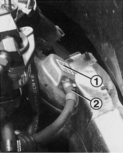
Pressure meter
pressure meter (3) mounted on a bracket on the front wall of the engine compartment. The cause of unstable idling may be a faulty or improperly fitted low pressure hose (1). Don't forget to also check the pin connection (2).
The suction pipe pressure sensor is mounted on the front wall on a bracket above the power module of the ignition system and is connected by a hose to the intake manifold. The voltage is applied to the resistor from the control device. The output voltage varies depending on the pressure established in the starting manifold, which determines the optimal load on the engine.
Injection system
Most of the elements of a single point injection system are located in this housing. The intake air passes through the injection housing, and here the nozzle injects fuel.
Injection valve
It opens with an electromagnet. In order for the fuel to be sprayed as best as possible, the valve has oblique outlets, passing through which gasoline hits the conical wall of the outlet, and there it swirls.
The amount of fuel is varied by changing the injection time. With each ignition pulse of the speed sensor, the valve produces an injection. If a small amount of fuel is required, the valve opens for a short time - less than a thousandth of a second. If the engine needs more fuel (cold or full load), then the injection valve opening time increases.
Lambda probe
It is installed in the exhaust pipe before the catalytic converter and is electrically heated to reach operating temperature faster after a cold start.
EGR valve
Only for Bendix injection system
This EGR diaphragm valve is connected through the intake manifold pipe to the exhaust manifold in the muffler. The diaphragm valve is controlled via a hose line by a solenoid valve. The electric valve is located behind the control device from which it receives the appropriate signals.
Air temperature sensor
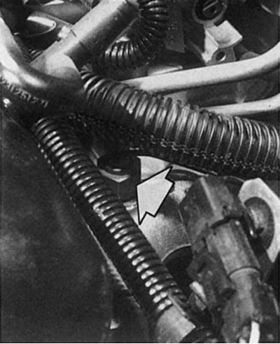
On Bendix single point injection system (left) the intake air temperature sensor is screwed into the intake manifold; on a Bosch single point injection system, it is located on a bracket in the throttle body. If only the intake air temperature sensor fails (shown by arrow) there is a failure in the process of creating the working mixture and the moment of ignition, due to which the engine loses power.
 |  |
The sensor works as a variable resistance with «negative temperature coefficient» (NTC), which means that the resistance will decrease with increasing temperature.
Intake air sensor: it is located on the side of the intake manifold in the Bendix system and measures the temperature of the combustible mixture there. On the Bosch throttle body, a sensor is located in the injector body and registers the temperature of the intake air.
Coolant sensor: it is in the intake manifold. When starting a cold engine, as well as during warm-up, data on the temperature of the coolant is needed for correct fuel metering and for ignition correction. On the 1.4 liter engine, this sensor has a similar function and also measures the temperature of the intake manifold.
The single point injection system works as follows:
Starting a cold engine: The control device receives data on the engine temperature from the coolant temperature sensor. The colder the engine, the longer the injection time to create a richer fuel mixture at engine start. The throttle position adjuster sets the desired throttle position.
Warm-up process: the temperature sensor reports the gradual heating of the coolant to the control device. Accordingly, the injection time is reduced. In this mode, the lambda signal is not transmitted, i.e. the working mixture is not optimal for the catalyst. The throttle position control keeps the throttle slightly open.
Idling: The idle switch in the throttle control element informs the control unit of the operating mode. At the same time, the throttle position control adjusts the idle speed. The speed drop that occurs when a powerful current consumer is switched on, such as when the steering wheel is fully turned with power, the automatic transmission speed is on or the air conditioner is on, the control unit equalizes by additional correction of the ignition timing.
Normal operation mode: the control device receives information about the engine speed by means of pulses from the speed sensor, from the pressure sensor, as well as about the position of the throttle valve. Based on this data, the control device evaluates the engine loads and mixes the required amount of fuel into the intake air through the injector.
Lambda control: when metering fuel, the fuel/air ratio is respected as λ = 1.
Acceleration: a sharp press on the accelerator pedal is recognized by the control unit by signals from a potentiometer or a full load switch as an acceleration process and immediately «enriches» working mixture.
Full load: starting from a certain throttle position, the control unit activates rich mode at full throttle. This means that more fuel is mixed into the working mixture. In enrichment mode, when the throttle is fully open, the lambda signal is ignored.
Overrun Mode: When driving downhill with the accelerator pedal released, the injection system conserves gasoline and cuts off the fuel supply as the engine has reached operating temperature. The control device recognizes this operating mode by the released gas pedal (throttle potentiometer or respectively idle switch in the servomotor), engine temperature sensor signals and engine speed greater than 1500-1900 rpm (speed sensor).