
- fuel supply, including a fuel tank, an electric fuel pump, a fuel filter, a fuel pressure regulator, pipelines and a fuel rail with injectors;
- air supply, including an air supply pipe, an air filter, a throttle assembly, an idle speed controller;
- capturing fuel vapors, including an adsorber and connecting pipelines.
The functional purpose of the supply system is to ensure the supply of the required amount of fuel to the engine in all operating modes. The engines are equipped with an electronic engine management system with distributed fuel injection. In the distributed injection system, the functions of mixture formation and dosing of the air-fuel mixture supply to the engine cylinders are separated: air is supplied by an air supply system consisting of a throttle assembly and an idle speed controller, and the amount of fuel required at each moment of engine operation is injected by injectors into the intake pipe. This control method makes it possible to ensure the optimal composition of the combustible mixture at each particular moment of engine operation, which allows obtaining maximum power with the lowest possible fuel consumption and low exhaust gas toxicity. Manages the fuel injection system (as well as the ignition system) an electronic unit that continuously monitors, with the help of appropriate sensors, the engine load, the vehicle speed, the thermal state of the engine, and the optimal combustion process in the engine cylinders.
The fuel vapor recovery system prevents the release of fuel vapors from the power supply system into the atmosphere, which adversely affect the environment.
The system uses the method of vapor absorption by a carbon adsorber. It is installed in a niche of the right front fender and is connected by pipelines to the fuel tank and intake pipe. On the adsorber cover there is an adsorber purge solenoid valve, which, according to the signals from the engine control unit, switches the operating modes of the system.
Fuel vapors from the fuel tank are constantly discharged through the pipeline and accumulate in the adsorber filled with activated carbon (adsorbent). When the engine is running, it regenerates (recovery) adsorbent by purging the adsorber with fresh air entering the system under the action of vacuum transmitted through the pipeline from the inlet pipe to the adsorber cavity when the valve is opened. The value of the valve opening, and hence the intensity of the purge of the adsorber, depend on the angle of rotation of the throttle valve and are determined by the vacuum that occurs in the cavity of the intake pipe of a running engine.
Fuel vapor from the adsorber through the pipeline enters the engine intake pipe and burns in the cylinders.
Malfunctions of the fuel vapor recovery system entail idle instability, engine shutdown, increased toxicity of exhaust gases and deterioration in driving performance of the vehicle.
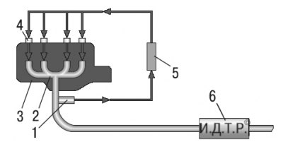
5.6. Air-fuel ratio control circuit diagram: 1 - oxygen concentration sensor in exhaust gases (Lambda probe); 2 - exhaust manifold; 3 - engine; 4 - nozzle; 5 - engine control unit; 6 – catalytic converter of the fulfilled gases
The main sensor for ensuring an optimal combustion process is the oxygen concentration sensor in the exhaust gases (Lambda probe). It is installed in the engine exhaust manifold and, together with the electronic unit and injectors, forms a circuit for adjusting the composition of the air-fuel mixture supplied to the engine (pic. 5.6). Based on the sensor signals, the engine control unit determines the amount of unburned oxygen in the exhaust gases and, accordingly, evaluates the optimal composition of the air-fuel mixture entering the engine cylinders at any given time. Having fixed the deviation of the composition from the optimal 1:14 (respectively fuel and air), providing the most efficient operation of the catalytic converter of exhaust gases, the control unit changes the composition of the mixture using injectors. As a result, the air-fuel ratio control loop is closed.
Some vehicles have two oxygen sensors, one in the exhaust manifold and one behind the catalytic converter. The first sensor is the control (Based on its signal, the ECU adjusts the fuel supply), and the second - diagnostic (focusing on its signal, the ECU evaluates the efficiency of the catalytic converter).
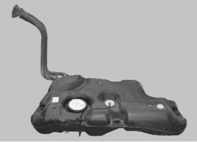
The fuel tank, molded from petrol-resistant plastic, is installed under the floor of the body in its rear part and is fastened with two bolts and two nuts. In order to prevent fuel vapor from entering the atmosphere, the tank is connected by a pipeline to the adsorber. An electric fuel pump is installed in the flanged hole in the upper part of the tank. From the pump, fuel is supplied through the pressure regulator to the fuel filter installed at the end of the fuel tank, and from there it enters the engine fuel rail mounted on the intake pipe. From the fuel rail, fuel is injected by injectors into the intake pipe.
The fuel lines of the power supply system are tubes connecting various elements of the system.
Attention! It is forbidden to replace steel pipelines with hoses, copper or aluminum pipes, as only steel pipelines satisfy the conditions of high pressure and vibration. The hoses of the power supply system are made using a special technology from oil and petrol resistant materials. Use of hoses other than those recommended may result in failure of the power system and, in some cases, fire. In the connections of pipelines with elements of the power system, round sealing rings are used. The use of seals of a different design is prohibited.
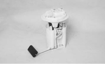
The fuel pump module includes an electric pump...
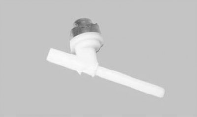
... a fuel pressure regulator that maintains a constant fuel pressure in the central passage of the fuel
ramps in all engine operating modes and does not allow excess pressure in the fuel rail...
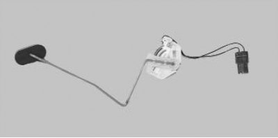
...and a fuel gauge sensor.
The fuel pump module provides fuel and is installed in the fuel tank, which reduces the possibility of vapor lock, since the fuel is supplied under pressure, not under vacuum.
The fuel pump is submersible type, with electric drive, rotary type. The non-separable pump cannot be repaired; if it fails, it must be replaced.
Fuel filter 1 (pic. 5.7) fine cleaning - full-flow, fixed with a clamp 7 on the fuel tank in its front part. The filter is non-separable, consists of a steel housing with a paper filter element.
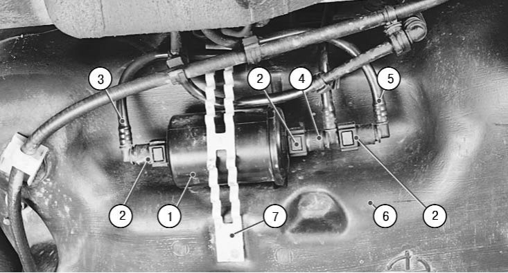
5.7. Location of the fuel filter on the car: 1 - fuel filter; 2 - tips of pipelines; 3 - fuel supply line; 4 - fuel drain pipeline; 5 - outlet fuel line; 6 – fuel tank; 7 – a collar of fastening of the fuel filter
Ramp 2 nozzles (pic. 5.8) is a cast hollow part with holes for installing injectors 3 and with an inlet fitting 5 for connecting a high-pressure fuel line. The injectors are sealed in their sockets with rubber rings 4 and secured with spring clamps 1. The assembly with injectors is inserted into the inlet pipe openings with injector shanks and secured with two bolts.
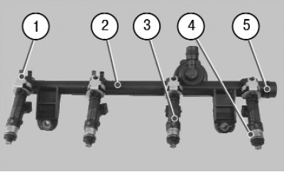
5.8. Injector rail: 1 - nozzle lock; 2 - ramp; 3 - nozzle; 4 - nozzle sealing ring; 5 - fitting for connecting the high pressure fuel line
nozzles (pic. 5.9) attached to the ramp from which fuel is supplied to them, and with their atomizers they enter the openings of the intake pipe. In the openings of the ramp and the inlet pipe, the nozzles are sealed with rubber sealing rings 1 and 2. The nozzle is designed for metered fuel injection into the engine cylinder and is a high-precision electromechanical valve. Pressurized fuel flows from the rail through channels inside the nozzle body to the shut-off valve. A spring compresses the check valve needle against the taper hole in the atomizer plate, keeping the valve in the closed position. The voltage supplied from the engine control unit through plug-in terminals 3 to the injector solenoid winding creates a magnetic field in it, which draws the core together with the shut-off valve needle into the solenoid. The conical annular hole in the atomizer plate opens and fuel is injected through the diffuser of the atomizer body into the inlet channel of the cylinder head and further into the engine cylinder. After the termination of the electrical impulse, the spring returns the core and the needle of the shut-off valve to its original state - the valve is closed. The amount of fuel injected by the injector depends on the duration of the electrical impulse.
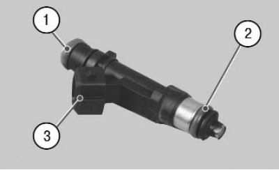
5.9. Fuel Injector: 1 - top sealing ring; 2 - lower sealing ring; 3 - plug terminals of the electromagnet winding
The fuel pressure regulator, installed in the fuel pump module, maintains a constant fuel pressure in the engine power supply system at all engine operating modes. The electric fuel pump supply is greater than necessary to keep the system working. Therefore, when the engine is running, part of the fuel is constantly drained into the fuel tank by means of a pressure regulator.
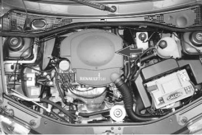
The air filter is installed in the center of the engine compartment.
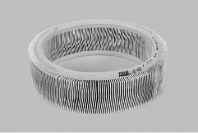
The filter element of the air filter is paper, round, with a large area of the filtering surface.
The throttle assembly is the simplest control device and serves to change the amount of main air supplied to the engine intake system. It is installed on the inlet flange of the inlet pipe. An air filter is put on the inlet pipe of the throttle assembly, the connections of the throttle assembly with the intake pipe and the air filter are sealed with rubber gaskets.
In the body of the throttle assembly, a hole is made for supplying additional air to the idle speed controller.
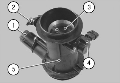
5.10. Throttle assembly: 1 - idle speed regulator; 2 - throttle actuator lever; 3 - throttle valve; 4 - throttle position sensor; 5 - throttle body
In building 5 (pic. 5.10) a damper 3 rotating on the axis is installed. At one end of the axis, a throttle position sensor 4 of the engine control system is installed, at the other end is lever 2, to which the intermediate thrust of the throttle actuator is connected. An idle speed controller 1 is fixed on the housing 5, which doses the air flow with the throttle closed.
During operation, the throttle assembly does not require maintenance and adjustment, only monitor the condition of the rubber seals to avoid air leakage.
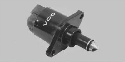
The idle speed controller maintains the set idle speed of the engine at a fully closed throttle during its start-up, warm-up and when the load changes when auxiliary equipment is turned on.
The regulator changes the amount of additional air supplied to the intake system in addition to the throttle, and is an electromechanical valve attached with two bolts to the flange of the throttle body. The valve seat of the regulator and channels made in the flange of the throttle assembly form a system for supplying additional air, bypassing the throttle valve.
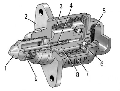
5.11. Idle speed controller: 1 - valve; 2 – regulator body; 3 - stator winding; 4 - lead screw; 5 - plug output of the stator winding; 6 - ball bearing; 7 - stator winding housing; 8 - rotor; 9 - spring
The engine control unit, having processed the signals from the sensors, determines the need to open valve 1 (pic. 5.11) regulator and transmits pulses to the plug output 5 of the winding 3 of the stator of the regulator. With each control pulse, the rotor 8 rotates at a certain angle, moving the valve 1 relative to the seat using the lead screw 4. Additional air enters the intake pipe through channels in the throttle assembly. By determining the vacuum in the engine intake pipe, the control unit seeks to maintain it at a given level by periodically opening and closing the idle speed control valve. This makes it possible to supply a constant amount of additional air to maintain a constant idle speed. By changing the opening and closing of the regulator valve, the control unit compensates for a significant increase or decrease in the amount of air supplied, caused by its suction through a leaky intake system or, conversely, by a clogged air filter.
The inclusion of additional units causes an increase in engine load, accompanied by a decrease in the idling speed and a change in the vacuum in the intake pipe, which is also compensated by the control unit using the regulator.