The fuel pump delivers fuel under pressure to the fuel rail, which serves as a reservoir for the injectors installed on each cylinder that inject fuel into the intake tracts.
The engine is equipped with a Siemens-Sirius fuel injection system. This is a distributed injection that delivers fuel in accordance with the order of the cylinders at the start of the intake stroke.
To obtain information about which of the cylinders is currently in the intake stroke, the ECU uses a single TDC and engine speed sensor, which determines:
- TDC of pistons of the first and fourth cylinders;
- TDC of pistons of the second and third cylinders.
The system includes two exhaust gas oxygen concentration sensors, one of which is installed before the catalytic converter, and the second - after it. Signals from the sensors inform the ECU about deviations from the normal combustion process of the mixture in the cylinders and are used to correct this process in order to optimize engine operation.
The coolant temperature sensor informs the ECU about the thermal state of the engine.
Air enters the system through the intake silencer, which is attached to the air filter. The engine air temperature sensor informs the ECU of the temperature of the air passing through the throttle valve.
[View the original on the specified resource RenaultBook]
The crankshaft position sensor informs the ECU about the engine speed and the position of the pistons in the cylinders.
The knock sensor informs the ECU about a deviation in the fuel combustion process, accompanied by detonation in the cylinders. The change in engine load is transmitted to the ECU by a pressure sensor installed in the intake manifold.
The ECU controls the engine idle speed via the idle speed controller (stepper motor), which is mounted on the throttle body. The regulator controls the opening of the bypass air channel, bypassing the throttle valve. If the throttle valve is closed (the fuel pedal is released), The ECU commands the regulator to control the air flow into the engine, thus regulating the idle speed.
The potentiometer mounted on the accelerator pedal informs the ECU about the position of the throttle valve at each specific moment of engine operation.
To correct the idle speed when additional load is applied (air conditioning, power steering pump) the sensor is designed to allow the ECU to increase the idle speed, thereby preventing the engine from stopping.
To improve the engine's environmental friendliness and increase its efficiency, a waste collection system is used (adsorption) fuel vapors with their subsequent combustion in the engine cylinders. The recirculation valve of this system is also controlled by the ECU.
When receiving information about an abnormal situation from the sensors, the ECU switches to the backup engine control mode. In this case, the ECU ignores abnormal signals and, using the remaining signals, issues commands to continue engine operation, although with a decrease in fuel efficiency and dynamics. In this case, a warning signal lights up on the instrument panel and a corresponding fault code is entered into the ECU memory.
The system has a built-in inertial fuel shut-off sensor that is triggered by an impact in the event of a traffic accident. The sensor stops the fuel pump, preventing gasoline from leaking if the fuel lines are damaged.
The ignition system works together with the fuel injection system according to the commands of the ECU.
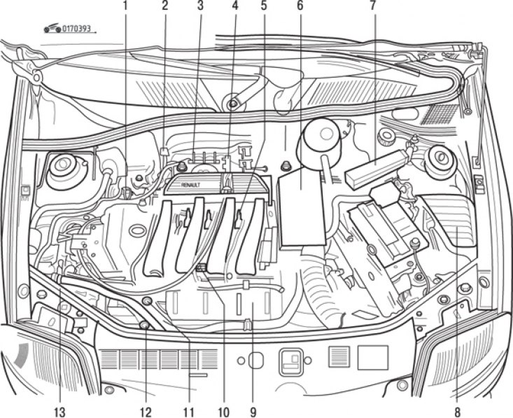
Fig. 3.93. Location of fuel injection system components in the engine compartment: 1 – pressure sensor; 2 – stepper motor of idle speed controller; 3 – throttle position sensor; 4 – upper oxygen concentration sensor; 5 – coils and spark plugs; 6 – coolant temperature sensor and top dead center sensor; 7 – Injection system control unit; 8 – power relay; 9 – knock sensor; 10 – air temperature sensor; 11 – fuel distribution rail and fuel pressure regulator; 12 – Power steering pressure relay; 13 – adsorber with electromagnetic valve
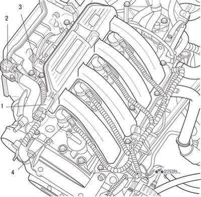
Fig. 3.94. Location of injection system elements on the engine: 1 – pressure sensor; 2 – stepper motor of idle speed controller; 3 – throttle position sensor; 4 – ignition coil
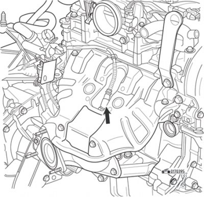
Fig. 3.95. Upper oxygen concentration sensor
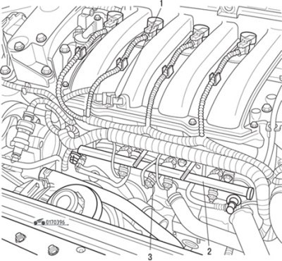
Fig. 3.96. Location on the engine of the sensor (1) for incoming air temperature, fuel rail (2), knock sensor (3)
The arrangement of the fuel injection system elements is shown in Fig. 3.93, 3.94, 3.95, 3.96.
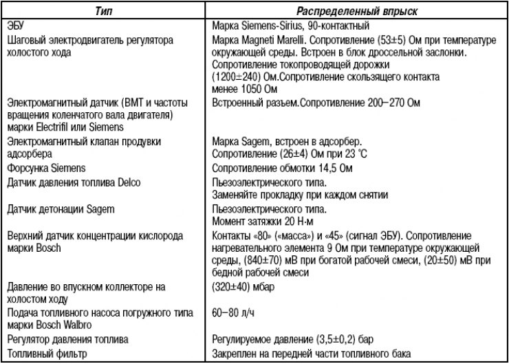
The technical characteristics of the injection system are given in Table 3.7.
Table 3.7. Technical characteristics of the injection system