



- relieve pressure in the fuel system;
- remove the wire from the negative terminal of the battery;
- lift the back seat;
- remove the metal cover on the rear floor to gain access to the pump cover;
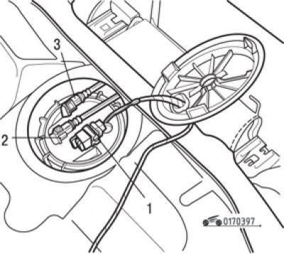
Fig. 3.97. Fuel pump cover: 1-pin connector; 2 – fuel supply pipeline; 3 – drain pipe
- disconnect the electrical connector (Fig. 3.97);
- disconnect the quick release fitting of the fuel supply line (green color);
- disconnect the quick release fitting of the drain pipe (red color). Plug the holes to prevent dirt from entering;
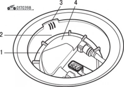
Fig. 3.98. Fuel pump cover marking: 1 – round nut for fastening the fuel pump; 2 – mark on the round nut; 3 – three marks on the fuel tank; 4 – mark on the fuel pump cover
- fix the marking for aligning the components of the unit (Fig. 3.98). Place a wide-blade screwdriver on the protrusion of the round nut and, lightly hitting it with a hammer, knock the nut out of place, and then unscrew it manually;
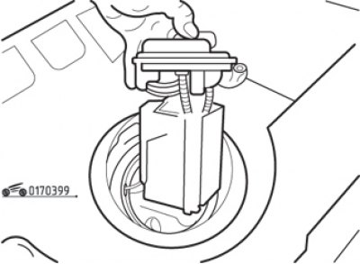
Fig. 3.99. Removing the fuel pump from the fuel tank
- carefully remove the fuel pump and level sensor assembly from the tank (Fig. 3.99);
- inspect the sealing gasket. If it is free from defects, it can be reused.
Note: If several hours must pass between removal and installation of this unit, tighten the nut on the tank to avoid deformation.
Installation procedure:
- clean the fuel pickup screen if necessary;
- install the sealing gasket on the top of the fuel tank;
- carefully place the pump into the tank;
- align the marks as shown in Fig. 3.99 and install the round nut. Tighten it securely and make sure the marks are aligned;
- snap the pipe fittings;
- connect the contact connector;
- install the hatch plug;
- perform the remaining operations in the reverse order of removal.