
Self check
Many types of injection system checks are not available to amateur motorists, since they cannot be done without the necessary instrumentation.
The control device cannot be tested at home. In practice, this device is very rarely faulty.
Sensors, switches, and wire connections are much more likely to fail. Therefore, in the event of a malfunction, it is advisable to proceed as follows:
1. Make sure the ignition is in order.
2. Check the power system.
3. Conduct an external inspection of the elements of the injection system.
4. If it was not possible to find a malfunction in this way, study the table «Trouble-shooting» at the end of the chapter, or have the injection system checked by a workshop where all the necessary instruments are available.
Visual inspection
1. Are the engine ventilation air hoses clogged, dirty or swollen?
2. Are there signs of fuel leakage on the fuel lines?
3. Check the pressure regulator for leaks.
4. Check the fuel return from the pressure regulator.
5. Is the injector gasket damaged?
6. Have the wire connectors been repeatedly disconnected and re-inserted into each other? Corrosion or incorrect connection can cause poor contact.
7. Examine attentively contact connections in separate elements of a design of system of injection. Do not bend the contacts, but only treat with a special cleaning aerosol.
Search for leaks
A leak in the intake system allows the so-called «erroneous» air, i.e. air that is not taken into account in the calculations of the control device and which interferes with the preparation of the combustible mixture. As a result, the working mixture becomes leaner uncontrollably. The easiest way to recognize this malfunction at idle is by fluctuating engine speed.
1. Check the low-pressure hoses for cracks and tight connections to the fittings. It is necessary to check all hoses that are connected to the injection system or to the intake manifold (pressure sensor, brake booster, intake air preheater, fuel mixture preparation system).
2. Warm up the engine and, leaving it to idle, open the hood.
3. Spray start fuel sprayer (For example, «launch pilot» «Startpilot») injection device in the flange to the intake manifold, gaskets between the flanges of the intake ducts and pipelines to the underpressure controlled housings (to disconnect the lambda probe connector).
4. If the engine speed changes when processing a certain place, then there is a leak there.
Checking individual elements
The following describes the test of individual elements of the injection system at home.
Recommendation: When working on the injection system, you must remember that the system remains under pressure for a long time after the engine has been switched off. Therefore, always keep a rag ready when unscrewing bolts and pipes so that gasoline does not splatter.
Checking the Throttle Position Control
- Disconnect the connector from the throttle position control.
- Bendix servo: to the contact «2» (counted from left to right) connect «mass» and to contact «3» 12 V.
- Bosch servomotor: connect a maximum voltage of 6 V to both upper connection pins of the servomotor (e.g. using a 4.5V battery); «–» minus up.
- Both motors: pushrod must extend fully.
- Change the poles of the connecting wire.
- The pusher must fully retract.
- If everything goes as described, then the throttle position control is good. If not, it must be replaced.
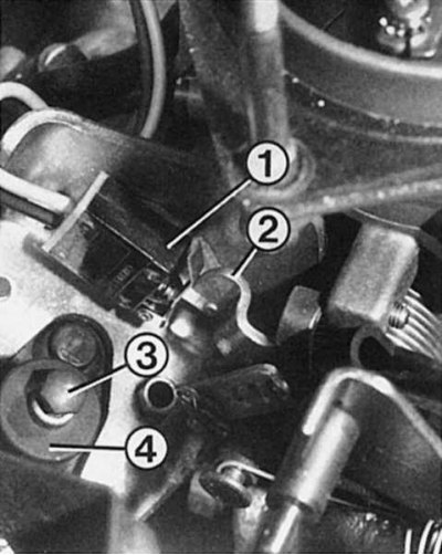 | 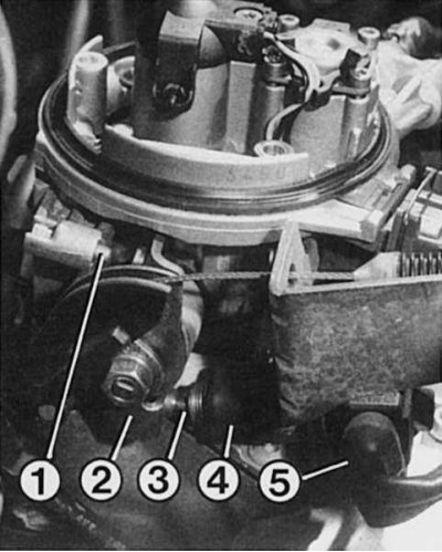 |
Left: On a Bendix single point injection system, opposite the idle speed limiter for the throttle valve (2) full load switch limiter is located (1). Pusher adjustment (3) throttle position controller (4) must be carried out in a workshop. Right: here the same for the Bosch single-point injection system: in front of the idle speed limiter (1) throttle valve is the limiter (2) pusher (3) throttle position controller (4). After disconnecting the contact (5) you need to check the operation of the engine.
Checking the performance of the idle switch
- Disconnect the throttle position control connector.
- Bendix servo: connect an ohmmeter to the servo pins.
- The resistance with the pusher contact disconnected should be 5 kΩ.
- With the pusher pin connected, the resistance should be 0.15 ohms.
- Bosch servomotor: connect an ohmmeter to the idle switch contacts.
- To do this, use the contacts on the five- and seven-pin block «1» and «2», counting from the right.
- Idle switch pressed: 0 ohm resistance.
- Idle switch not pressed: resistance tends to infinity.
Testing the Bendix Full Load Switch Regulator
- Disconnect the switch connector.
- With the switch in the closed position, the resistance should tend to infinity.
- In the position of maximum fuel supply (pressed switch) resistance should be 0.15 ohm.
Bosch injection throttle potentiometer test
- Disconnect the throttle potentiometer connector.
- According to the table, connect an ohmmeter to the indicated two contacts.
- If the specified values are not achieved, the throttle valve potentiometer is faulty. It cannot be replaced individually. It is necessary to completely replace the lower part of the injection system housing.
Terminals | Verification conditions | Resistance | |
Manual Transmission | Automatic transmission | ||
1 + 5 | 1 + 7 | — | 520-1300 ohm |
1 + 2 | 1 + 2 | From fully closed to 1/4 open throttle: resistance increases, then becomes constant. | 600-3500 ohm |
1 + 4 | 1 + 6 | From fully closed to 1/4 throttle open: resistance then increases. | 600-6600 ohm |
Injector test
1. Disconnect the fittings and remove the air filter.
2. Start a warm engine and let it idle.
3. Look at the jet of fuel from the injector. It should be uniform and directed towards the throttle valve.
4. Stop the engine to check the tightness of the valve.
5. When the engine is not running, no more than 2 drops of fuel per minute can flow from the nozzle.
6. You carry out a further check if the engine cannot be started.
7. Check the electrical relay of the system.
8. Disconnect branch pipes and remove the air filter.
9. Turn the engine over with a starter.
10. You should see the injector injecting fuel.
11. If not, disconnect the connectors on top of the injection system.
12. Connect an ohmmeter to both connecting pins.
13. When the ambient temperature is between +15°C and 30°C, the resistance should be about 1.2 ohm (Bosch) and respectively 1.4 ohm (Bendix), otherwise the injector is defective. Remove the TORX bolt and replace the injector.
14. Check for a contact in the electrical circuit of the injector if it does not inject fuel despite the required resistance.
15. Connect the LED voltage probe, without using any other devices, to both pins on the removed connector.
16. Turn on the starter: the LED should flash; if not, then somewhere there is a wire break or a malfunctioning control device.
Checking the fuel cut-off during engine braking
1. Disconnect the fittings and remove the air filter.
2. Start the engine, let it run for a while at over 3000 rpm, and close the throttle quickly.
3. At this point, the jet of fuel from the nozzle should be interrupted for a short time. In this case, everything works fine.
4. If not, check the throttle switch and control device yourself or have it checked by a workshop.
Checking temperature sensors
1. Intake air temperature sensor (Bosch throttle body): Disconnect the connector at the top of the injection system.
2. Connect an ohmmeter to both pins.
3. Coolant temperature sensor (engine type «F») or intake manifold (engine type «WITH»): Disconnect the connector from the two-pole sensor.
4. Connect an ohmmeter to the sensor contacts.
5. Both types of sensor: determine the resistance value and compare it with the table below.
6. If the measurement results match the data in the table, the sensor is working normally.
7. Coolant or intake manifold temperature sensor and mixture temperature sensor: expose the contact at the sensor «+» (wire color, see Electrical circuits). The pin block remains on.
8. Connect a voltmeter: install a thin test tip on a bare contact, connect the other to ground.
9. Start a cold engine and let it warm up.
10. Watch the voltmeter needle - the value should constantly increase.
11. If the arrow does not move, then the temperature sensor is defective.
| Temperature measurement | 0±1°C | 20±1°C | 40±1°C | 80±1°C | 90±1°C |
| Intake air temperature sensor 1.8 liter engine | 5.29-6.49 kΩ | 2.4-2.6 kOhm | 1.07-1.27 kOhm | — | — |
Mixture temperature sensor 1.4-/1.7-liter engine | 7.47-11.97 kΩ | 3.06-4.04 kOhm | 1.29-1.65 kOhm | — | — |
| Intake manifold temperature sensor 1.4 liter engine | — | 3.06-4.04 kOhm | 1.31-1.60 kOhm | 0.30-0.37 kOhm | 0.21-0.27 kOhm |
| Coolant temperature sensor 1.7-/1.8 liter engine | — | 3.06-4.04 kOhm | 1.31-1.60 kOhm | 0.30-0.37 kOhm | 0.21-0.27 kOhm |
Fuel pressure check
1. Fuel pressure can only be accurately determined with a special measuring device (in a car repair shop).
2. If you suspect an incorrect fuel pressure, disassemble the pressure regulator: unscrew the 4 TORX bolts (bolt with knurled thread for socket, star wrench).
3. Check if the membrane is damaged and if there is dirt deposited.