
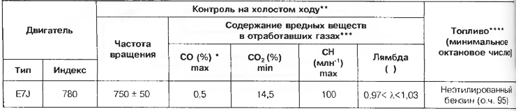
* At 2500 rpm, the CO content should not exceed 0.3%.
** When the coolant temperature is above 80°C after the engine has been running steadily at 2500 rpm for approximately 30 seconds. The check should be carried out after the transition to idling.
*** See country-specific specifications for guideline values.
**** Use of unleaded petrol is acceptable. 91.
Table 3.7
Elements of the injection system
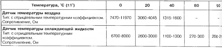
Table 3.8
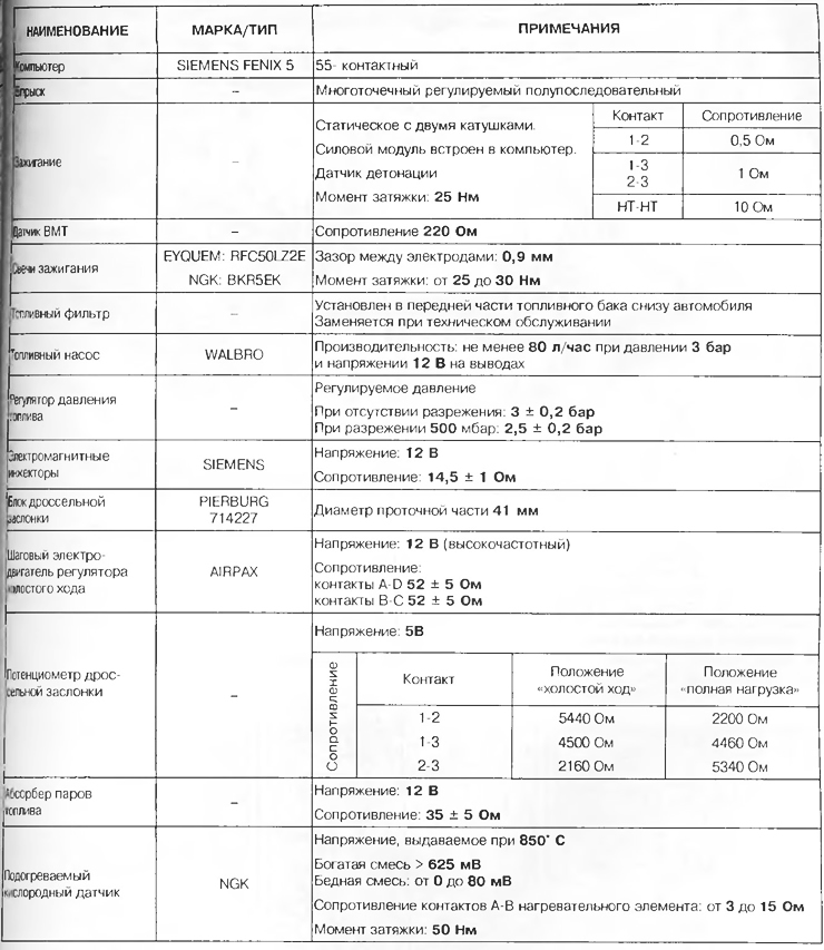
Features of the injection system:
- 55-pin computer SIEMENS FENIX 5;
- multi-point injection operating in semi-sequential mode. Pair control of injectors (first injectors for cylinders 1 and 4, then injectors for cylinders 2 and 3):
- static ignition system with two coils;
- solenoid valve for emptying the absorber, controlled by the law of cyclic opening;
- configuring the computer depending on the type of gearbox (mechanical or automatic);
- idling mode correction depending on: the presence of an air conditioner; power steering pressure switch signals; battery voltage;
- signal lamp of the injection system in the instrument panel;
- maximum engine speed: in 1st, 2nd, 3rd gears - 6200 rpm; in 4th, 5th gears - 6000 rpm.
Attention! The use of a second generation anti-theft system requires a special technique for replacing the injection computer.
Location of injection system elements
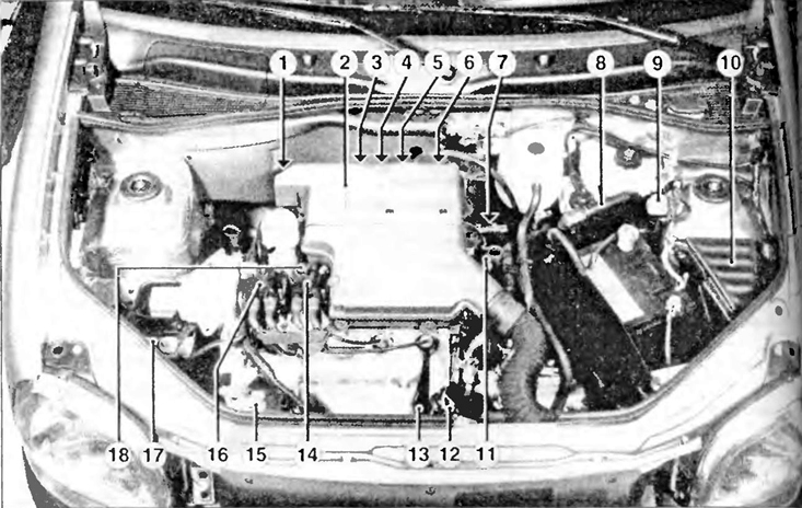
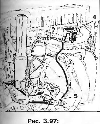
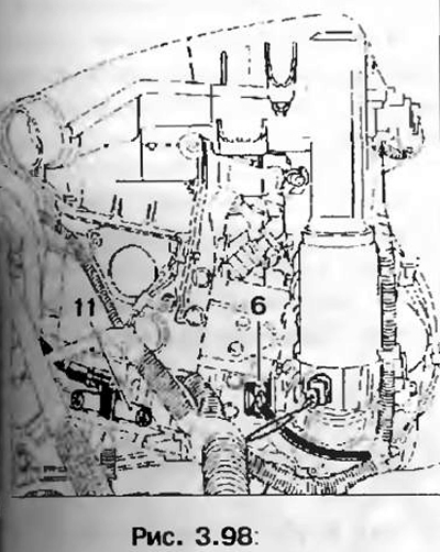
Pic. 3.92. The location of the elements of the injection system in the engine compartment:
1 - Solenoid valve for fuel vapor recovery;
2 - Air filter;
3 - Knock sensor;
4 - Absolute pressure sensor;
5 - Stepping motor of the idle speed controller;
6 - Throttle position potentiometer;
7 - Air temperature sensor;
8 - Injection computer;
9 - Inertial switch;
10 - Fuel pump relay;
11 - TDC sensor;
12 - Coolant temperature sensor;
13 - Oxygen sensor;
14 - Ignition coil for cylinders 2-3;
15 - Power steering pressure switch;
16 - Ignition coil for cylinders 1-4;
17 - Fuel vapor absorber,
18 - Noise filter capacitor.
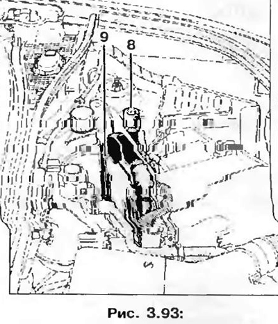
8 - Injection computer;
9 - Inertial switch.
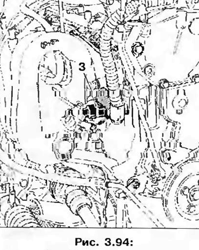
3 - Knock sensor (tightening torque: 25 Nm).
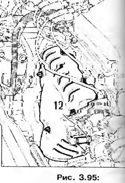
12 - Coolant temperature sensor.
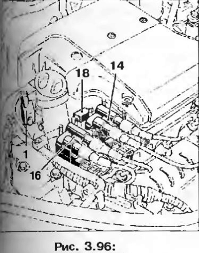
1 - Solenoid valve of the fuel vapor recovery system;
14 - Ignition coil for cylinders 2-3;
16 - Ignition coil for cylinders 1-4:
18 - Noise filter capacitor.
4 - Absolute pressure sensor;
5 - Stepper motor of the idle speed controller;
7 - Air temperature sensor.
6 - Throttle position potentiometer;
11 - TDC sensor.
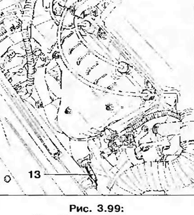
13 - Oxygen sensor (tightening torque: 45 Nm).
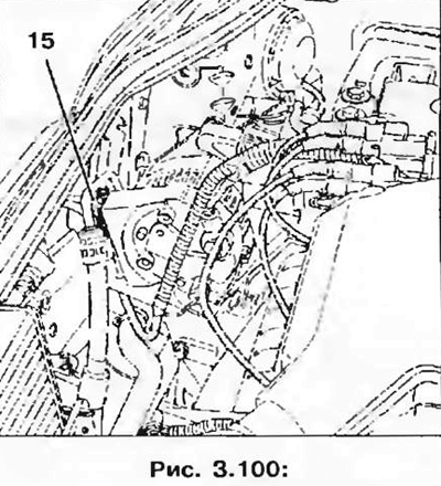
15 - Power steering pressure switch.
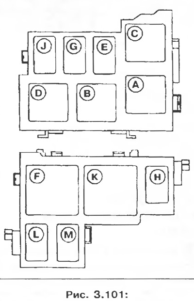
K - Relay for a group of electric fans (air conditioning option);
L - Fuel pump relay;
M - Relay for a group of electric fans (option without air conditioning) or low fan speed (air conditioning option).