
Technical data
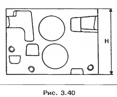
1. Cylinder head
Cylinder head height mm: H = 113.5.
The maximum allowable deformation of the mating surface, mm: 0.05.
Combustion chamber volume with valves and spark plug, cm3: 26,25±0,6.
2. Valve guides
Nominal inner diameter, mm: 7.
Nominal diameter of the seat in the cylinder head, mm: 12.
Attention! The intake and exhaust valve guides have valve stem seals that must be replaced each time the valve train is disassembled.
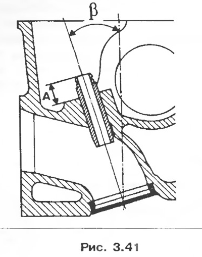
The inclination of the guide sleeves of the intake and exhaust valves: β = 17°.
The position of the guide bushings of the intake and exhaust valves relative to the lower support ends of the valve springs (without bottom plate), mm: A = 12.
3. Valve springs
Nominal size (black)
Free length, mm: 46.64
Length under load, mm:
- 270 H 37;
- 536 N 27.5.
The length of the spring at full compression of the coils, mm: 23.63;
Wire diameter, mm: 3.8
Inner diameter, mm: 21.5.
Repair size (orange)
Free length, mm: 44.93;
Length under load, mm:
- 270 H 37;
- 650 N 27.6.
The length of the spring at full compression of the coils, mm: 26.01.
Wire diameter, mm: 4
Inner diameter, mm: 21.5.
4. Valves
Rod diameter, mm: 7
Chamfer Angle:
- inlet valve: 120°;
- outlet valve: 90°.
Head diameter, mm:
- inlet valve: 37.5±0.1;
- exhaust valve: 33.5±0.1.
Attention! When replacing valves, the new valves installed must have the same part number 1 as the previous valves to prevent damage to the valves and seats.
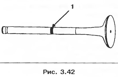
The same part number can have multiple markings, in which case all valves are fully interchangeable.
Verify that new valves with different markings from removed valves have the same part number.
5. Valve seats
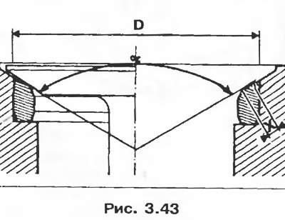
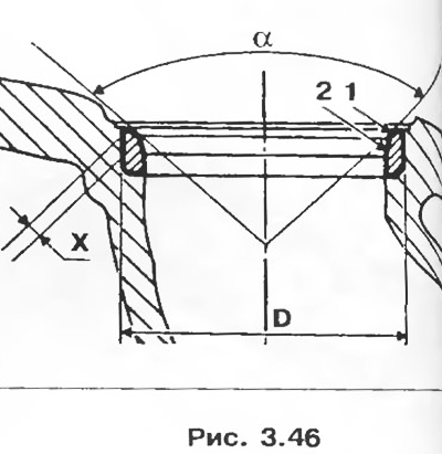
Chamfer Angle:
- Intake valves α = 120°.
- Exhaust valves α = 90°.
- Width of a working facet of a saddle, mm.
- Inlet valves X = 1.7 + 0.1.
- Exhaust valves X = 1.7±0.1.
- Saddle outer diameter D, mm.
- Intake valves 38.5.
- Exhaust valves 34.5.
6. Camshaft
Axial clearance, mm: 0.06-0.15.
Number of bearings: 5.
7. Parts to be replaced when removed:
- All seals and gaskets.
- Valve guides.
- Camshaft pulley bolt.
- Bolt of fastening of a head of the block of cylinders.
Disassembly
1. Remove the cylinder head (see section «Cylinder head gasket»).
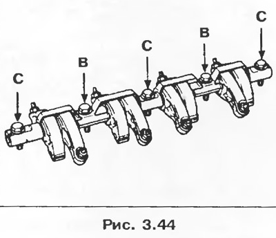
2. Remove the bolts securing the rocker arm axle and the rocker arm axle, after marking the position of the rocker arms and bolts on it:
- B - solid bolts;
- C - hollow bolts.
3. Remove:
- camshaft seal;
- camshaft thrust flange.
4. Remove the camshaft.
5. Remove the thermostat housing.
6. Remove spark plugs.
7. Remove the camshaft sprocket after fixing it with tool Mot 799-01.
8. Compress the valve springs (example, with tool FAC U43L)). Remove crackers, top plates, springs, valves, valve stem seals using special pliers 1335 and bottom cymbals.
9. Clean the cylinder head and check the deformation of the mating surface (see «Cylinder head gasket»).
Valve seat grinding
Inlet valves X = 1.7±α = 120°.
Grinding the chamfer of shaft 1 is done with a cutter with an angle of 31, reduce the width of the chamfer by processing the chamfer with a cutter with an angle of 75°to obtain the width X.
Exhaust valves X = 1.7±α = 90°.
Grinding the working chamfer of shaft 1 is done with a cutter with an angle of 46°, reduce the width of the working chamfer by processing it with a cutter with an angle of 65 to obtain the width X.
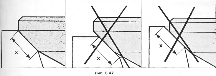
Attention! Check that the valve is seated correctly (pic. 3.47).
Assembly
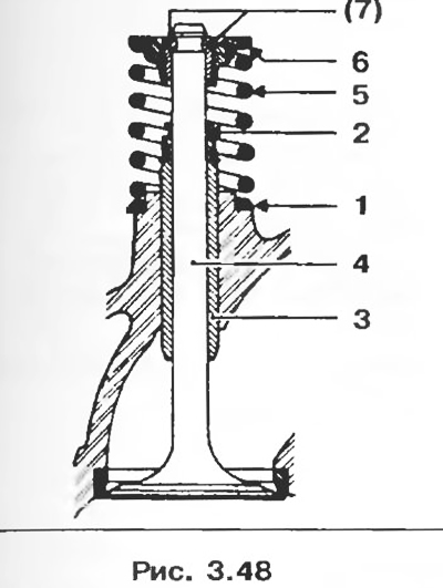
1. Lubricate all parts.
2. Establish the bottom plates of springs of valves.
3. Using a tubular socket wrench 11 mm, install the valve stem seals 2 on the valve guides 3.
4. Install:
- new valves 4;
- springs 5 (same for intake and exhaust valves);
- top plates 6.
5. Compress the springs.
6. Install crackers 7 (same for intake and exhaust valves).
7. Lubricate the camshaft.
8. Install the camshaft and its thrust flange.
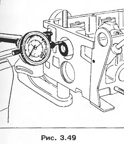
9. Check the axial clearance, which should be 0.06-0.015 mm, if not, the flange or camshaft is the cause.
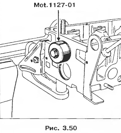
10. Install the oil seal using the lot installer. 1127-01, which allows you to shift the fit of the working edge of the oil seal on the camshaft.
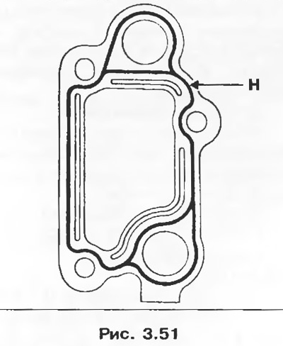
11. Install the thermostat housing, sealing it with Loctite 518 sealant. The sealant bead H must have a width of 0.6 to 1 mm (pic. 3.51).
12. Install the camshaft pulley, securing it with tool Mot. 799-01 and tightening the bolt with a torque of 45 Nm (lubricate the threads and the surface under the head of the bolt with oil).
13. Check up a condition of surfaces of rollers and bolts of yokes. Make sure that the lubrication holes of the cams and the heels of the rocker arms are not clogged. Replace worn parts. Install the rocker shaft so that mark 1 faces the timing gear.
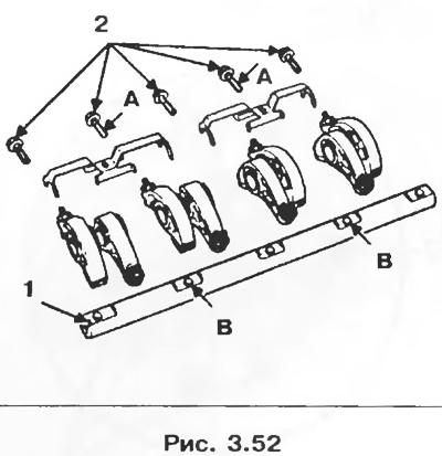
Note. Bolts A are available in two sizes M8 x 100 and M8 x 125.
Install the bolts 2 for fastening the rocker arm axle and tighten them to a torque of 23 Nm, having previously lubricated the threads and surfaces under the bolt heads with engine oil.