
1. Pistons
The piston pin is pressed into the upper head of the connecting rod and rotates freely in the piston bosses.
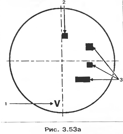
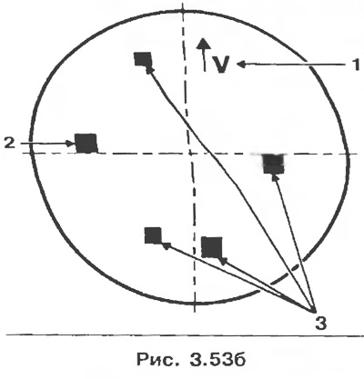
Fitting direction: Arrow points towards flywheel.
SMP piston
Piston
Arrow 1 indicates installation direction towards flywheel.
The size group of the piston is indicated by label 2 (piston group A-B-C).
Labels 3 are for the supplier.
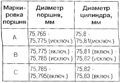
Table 3.2. Selection of pistons for cylinder liners
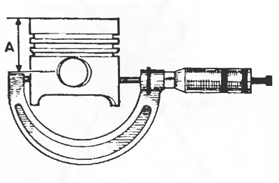
The piston diameter should be measured at distance A = piston crown.
2. Piston pins
Control dimensions, mm:
- length 60;
- outer diameter 19;
- inner diameter 11.
3. Piston rings
Thickness, mm:
- top compression ring 1.5;
- lower compression ring 1.75;
- oil ring 3.
4. Connecting rods
Lateral clearance of the lower head of the connecting rod, mm: 0.310-0.572.
Table 3.3
Attention! To avoid cracking the connecting rod, do not use a center punch for marking. Use an indelible pencil.
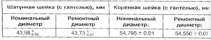
5. Cylinder liners
Use wetted type cylinder liners. They are equipped with J O-rings at the base.
Control dimensions, mm:
- sleeve height: H2 = 130;
- inner diameter: 75.8+0.030;
- centering diameter D = 80.6;
- protrusion of sleeves without sealant, X = 0.02-0.09;
- sleeve height H1 = 91.5 + 0.035 + 0.005;
- depth of the cylinder block: k1 = 91.5-0.015-0.055.
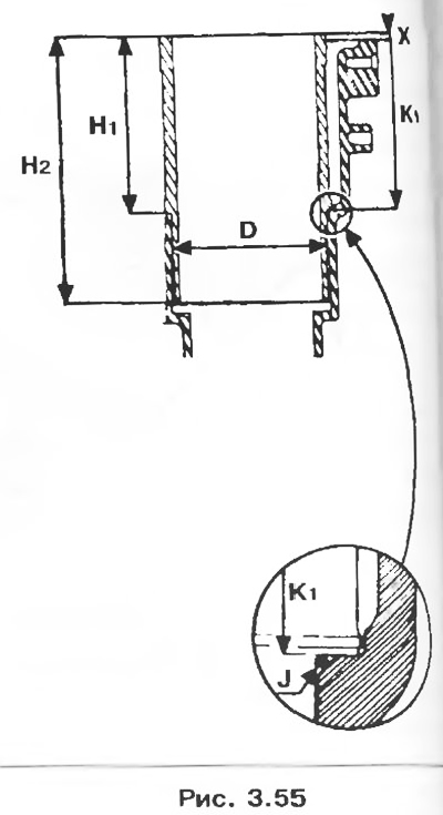
6. Crankshaft
Number of main bearings 5.
Axial clearance, mm:
- 0.045-0.852 with wear;
- 0.045-0.252 without wear.
There are persistent half rings of various thicknesses.
When grinding, the fillets on the surface must remain intact in areas forming an angle of 140° (pic. 3.56, arrows)
7. Parts to be replaced when removed
All seals and gaskets.
- Flywheel bolts.
- Connecting rod cap bolts.
- Crankshaft mounting bolts.
Disassembly
1. Remove the power unit.
2. Mount the motor on the base plate Mot. 792-03 rods Mot.1132. (pic. 3.15, 3.16).
3. Drain:
- oil from the engine.
- coolant from the cylinder block (with drain plugs).
4. Replace drain plugs.
5. Remove:
- engine wiring;
- generator and its belt.
2. Remove the cylinder head (see section «Cylinder head gasket»).
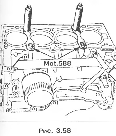
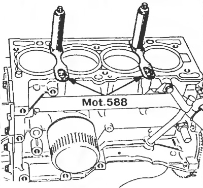
3. Install flanges Mot. 588 for holding cylinder liners.
4. Remove:
- coolant pipe and dipstick guide; they are equipped with O-rings, which must be replaced after each removal;
- clutch mechanism and driven disc;
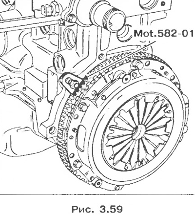
- flywheel by locking it with tool Mot. 582-01.
5. Remove the oil pan
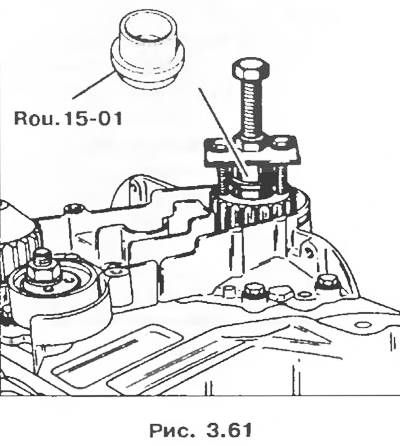
6. Remove the crankshaft sprocket. If necessary, use a locally made tool in conjunction with the Rou Shaft Protector. 15-01.
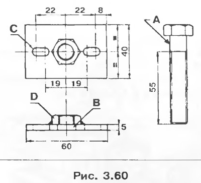
- A bolt with a diameter of 12 mm, thread pitch 1.75 mm.
- In one hole, diameter 13 mm.
- With two holes, diameter 6.5mm.
- D Welded nut Ø 12 mm, thread pitch 1.75 mm.
Note. The crankshaft sprocket can be installed in one of two ways (the two mounts are not interchangeable):
- - a pulley with a keyway on the crankshaft;
- - a pulley with a keyway in the pulley itself.
7. Remove the crankshaft oil seal cover.
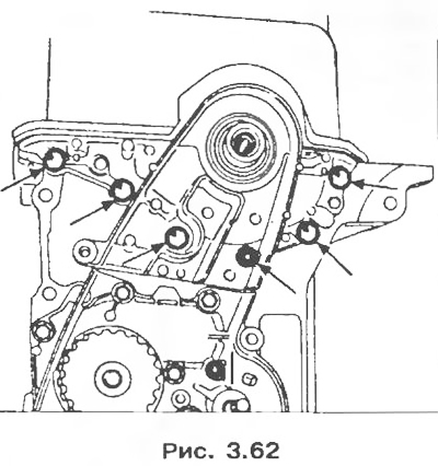
8. Remove:
- tension roller;
- coolant pump.
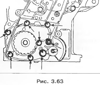
9. Remove:
- three bolts for fastening the oil pump drive gear, then the gear and chain;
- oil pump.
Mark the connecting rod caps in relation to their shafts.
Attention! To prevent cracks in the connecting rods, do not use a punch for marking. Use an indelible pencil.
10. Remove:
- covers and liners of the lower heads of connecting rods;
- flanges for holding cylinder liners Mot. 588;
- group «sleeve-piston-rod»;
- main bearing caps with their liners (tag them);
- crankshaft (keep the side thrust rings).
2. Fix the cylinder liners with tool Mot. 588.
3. Install bearing shells. The connecting rod bearing shells are the same. The crankshaft main bearing shells are grooved and mounted on the cylinder block. The #5 top bearing shell is special and also has a groove.

4. Establish a cranked shaft and lateral persistent half rings.
5. Lubricate the connecting rod and main journals of the crankshaft with engine oil.
6. Establish covers of radical bearings of a cranked shaft.
7. Apply a thin coat of RHODORSEAL 5661 to bearing #1 in area K (pic. 3.77) and tighten the fastening bolts with a torque of 25 Nm, then tighten by an angle of 43±6°.
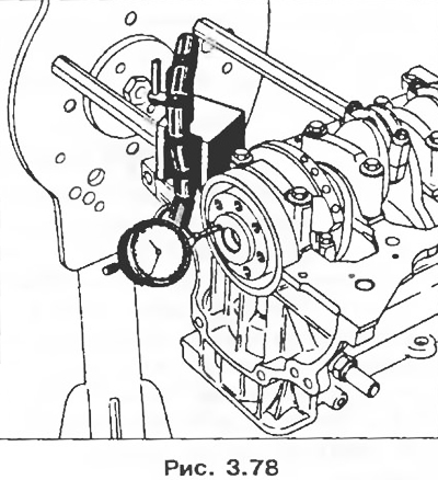
8. Check the axial clearance of the crankshaft:
- 0.045-0.852 mm in the presence of wear;
- 0.045-0.252 mm without wear.
The spare parts warehouse supplies thrust half rings of the following thickness, mm: 2.80; 2.85; 2.90; 2.95.
9. Install the connecting rod bearing caps and tighten the nuts to 42 Nm.
10. Check:
- axial clearance of connecting rods;
- correct rotation of the crank mechanism.
11. Install:
- oil pump, making sure that the centering sleeves are present, and tighten the bolts with a torque of 25 Nm;
- two gears and the oil pump drive chain, tighten the three bolts securing the gear to the hub with a torque of 10 Nm.
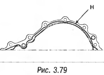
12. Install the crankshaft toe cover, reinforcing it with Loctite 518 sealant. The bead H of the sealant should have a width of 0.6 mm to 1 mm (pic. 3.79).
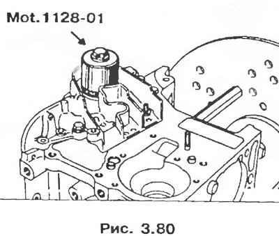
13. Install the crankshaft oil seal using tool Mot. 1128-01, lubricate the lip and outer surface of the seal with oil. Turn over the spacer sleeve if there is a groove on the bearing surface of the crankshaft nose at the place where the old oil seal was installed.
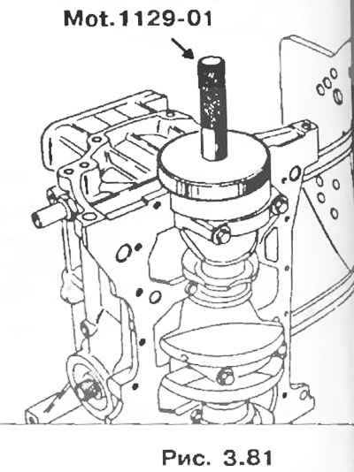
14. Install the crankshaft oil seal (bearing #1), using tool Mot. 1129-01 this tool allows you to align the oil seal to the crankshaft. Lubricate the seal lip and outer surface of the seal.
15. Install the oil pan and tighten the mounting bolts to 10 Nm.
Note. The sump is sealed with special aftermarket gaskets, except for the E7J 764 engine, which uses RHODORSEAL 5661 sealant. The sealant bead must be wide.
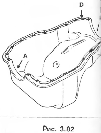
Remember to replace the two semi-circular seals in areas A with new ones and apply AUTOFORM sealant to the bearing surface of the flywheel with crankshaft.
16. Fit the flywheel and lock it with tool Mot. 582-01. Apply a drop of Loctite FRENETANCH sealant and tighten them with a torque of 50-55 Nm.