
Required special tools and fixtures
- Mot. 591-02 Magnetic base pointer for angular bolt tightening.
- Mot. 591-04 Angle wrench for tightening bolts.
- Mot. 1135-01 Fitted for tensioning the gas timing belt.
- Mot. 1273 Belt tension gauge.
- Engine maintenance tool.
Tightening torques, Nm
- Wheel bolts: 90.
- Crankshaft pulley bolt: 20 + 68°± 6°.
- Nut of fastening of a tension roller: 50.
- Bolt of fastening of the upper bracket of the suspension support of the engine: 62.
- Nut of fastening of the upper bracket of the support of the pendulum suspension of the engine: 44.
Removing
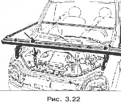
1. Place the vehicle on a two post lift.
2. Disconnect the battery.
3. Install fit to maintain the engine.
4. Remove:
- front right wheel, as well as a mudguard;
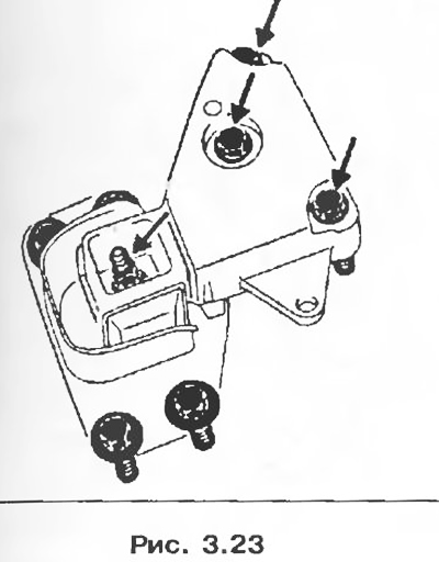
- upper bracket for the engine pendulum mount.
5. Remove:
- alternator drive belt and power steering pump;
- crankshaft pulleys, as well as the hub;
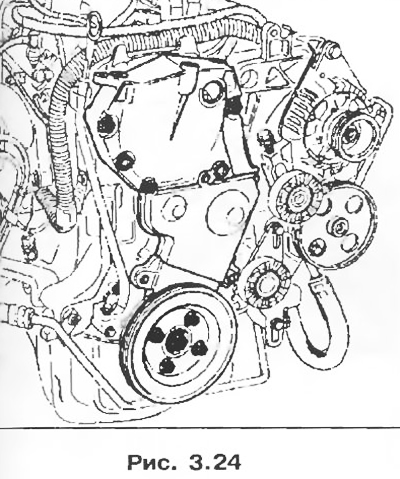
- timing cover.
6. Set the engine crankshaft to the timing adjustment position.
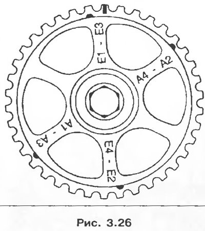
7. Align the L mark on the crankshaft sprocket with the M mark, and the N·mark on the camshaft sprocket should be in the position shown in the figure below.
8. Loosen the nut O and turn the shaft counterclockwise to loosen the belt tension, then remove the belt (1 direction of rotation of the tension roller).
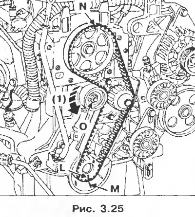
Attention! There are 5 marks on the camshaft pulley; only a rectangular mark applied on the side of the tooth corresponds to the position of the TDC; the rest of the marks are designed to adjust the clearances in the valve drive mechanism.
Installation
1. An arrow showing the direction of rotation is painted on the outside of the belt, as well as two adjustment marks.
2. Check that the engine crankshaft is in the position corresponding to the timing adjustment.
3. Align the marks on the belt with the marks on the toothed pulleys.
4. Begin to install the belt from the crankshaft sprocket, observing the belt installation direction.
5. Using tool Mot. 1135-01 tighten the belt until the set value is obtained (see chapter «Maintenance»).
6. Tighten the nut O of the tension roller with a torque of 50 Nm.
Attention! To prevent spontaneous unscrewing of the nut of the tension roller axle and, as a result, failure of the engine, strictly observe the tightening torque of the nut (50 Nm).
7. Install in the reverse order of removal.
8. Install the crankshaft pulley and tighten the bolt with a torque of 20 Nm, and then tighten it by 68±6°.
9. Install the accessory drive belt and tighten it (see chapter «Maintenance»).
Attention! Do not reinstall a removed belt, it should be replaced with a new one.