
Proper connection is essential for trouble-free operation (1). When putting on a multi-pin connector, always check that the spring stop is correctly installed.
 |  |
The following paragraphs describe injection system checks that you can carry out yourself using simple measuring devices and instruments. Leave the rest to the specialists from the Renault workshop.
Nozzles
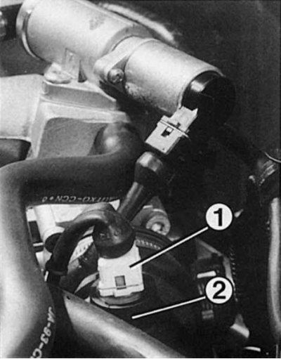
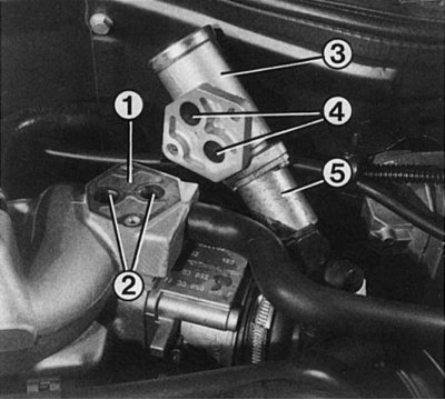
Nozzle 1.8-liter engine
1 - pin connection with a spring stopper; 2 - distribution fuel pipeline; 3 - nozzle; 4 — a safety collar of a nozzle on the distributive fuel pipeline.
When removing the injectors, all the mentioned elements must also be removed.
Sectional nozzle
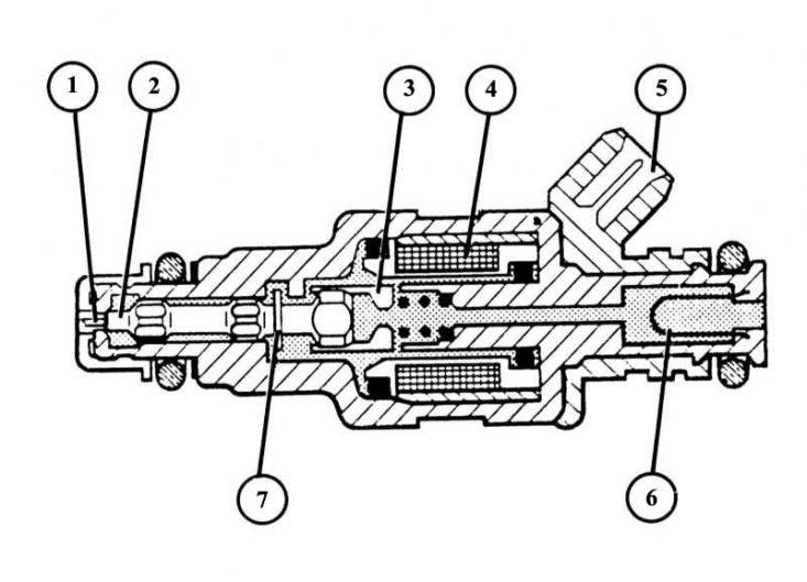
1 - rod entering the hole of the pin atomizer; 2 - valve needle; 3 - magnet thrust; 4 - magnet winding; 5 - plug connection; 6 - fuel filter; 7 - thrust ring.
If there is a suspicion that one of the nozzles is not working, first of all, try to identify the faulty nozzle by touch by hand. A defective injector does not vibrate when the engine is running. The check must be carried out on a cold engine.
1. Voltage control: disconnect the injector pins, connect the LED voltage probe (no test lights) to the well. Start the engine: the LED in the voltage tester should flash, if not, then there is no voltage or the control device is faulty. In this case, it is necessary to resort to the services of a car repair shop, since conventional measuring instruments are not enough for such control.
2. Resistance measurement: Disconnect the injector pins, insert an ohmmeter into both injector pins.
3. At 20°C, the resistance should be between 2 and 3 ohms.
4. If the resistance value obtained differs greatly from that indicated above, the nozzle must be replaced.
5. Leak test: Remove the fuel distribution line along with the injectors.
6. Disconnect all injector pin blocks, leave piping connected.
7. Switch the ignition on and off several times to start the fuel pump and pressurize the power system.
8. Watch the nozzles.
9. No more than one drop of fuel can leak from each valve. Otherwise, replace this injector.
10. Jet test: remove the fuel distribution pipe with injectors.
11. Disconnect from the nozzles which are not subject to check, pin blocks - fuel pipelines have to remain attached to all atomizers.
12. Place a container under the injector to be tested.
13. Turn on the ignition.
14. Fuel should be sprayed conically and continuously from the nozzle.
15. Check other injectors.
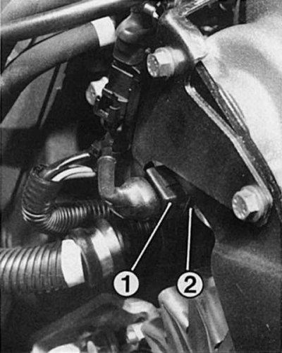
Start fuel valve
16 valve engine
The starting fuel valve is screwed in from below between the 1st and 2nd cylinders in the combined suction pipe. In order to check the operation of the valve, it must be unscrewed.
1. Disconnect the fuel start valve connector.
2. Unscrew the fuel line from the valve after removing the hose clamp.
3. Remove valve (you need to unscrew the two 5 mm hex bolts).
4. To test the valve, the fuel line must be connected.
5. Insert the valve into the measuring cup.
6. Turn on the fuel pump. To do this, connect the terminal to the battery and in the pin block of the fuel pump relay close with a thick insulated wire (section not less than 5 mm) contacts «3» (red wire) And «5» (brown wire).
7. Starting fuel valve must not inject fuel (take care of your eyes!).
8. Connect the pilot wire from the starting fuel valve to the positive and negative poles of the battery.
9. The valve should now spray fuel into the measuring cup.
10. Install the valve with the battery disconnected.
11. Before final assembly, connect the battery and turn on the fuel pump as described above to check the tightness of the fuel line connection to the starting fuel valve.
12. If fuel is leaking, replace the seals.
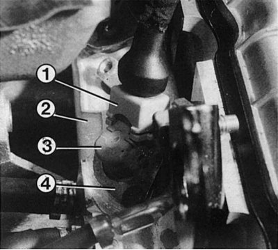
Idle air control valve
1 - gasket between flanges; 2 - bypass holes in the throttle body leading to the intake manifold; 3 - idle control valve; 4 - bypass holes of the gas channels of the idle control valve. When installed, they must fit exactly into the holes in the suction pipe assembly; 5 - magnet switch.
1. Start the engine and let it idle.
2. Turn on the most powerful current consumer, if possible, or completely turn the steering wheel. In this case, the idling speed will decrease for a while, but then it will automatically adjust to the prescribed value.
3. When disconnecting the plug connection, the engine must stop. Otherwise, replace the valve as it is not repairable.
4. Intake air temperature sensor: Disconnect the connectors from the intake air hose or from the intake manifold.
5. Connect an ohmmeter to both external plug contacts.
Checking temperature sensors
Coolant temperature sensor: Disconnect the pin blocks from the two-pole sensor next to the thermostat housing. Connect an ohmmeter to the pins of the sensor.
Both sensors: determine the resistance value and compare it with the data in the table below.
If the measurement results match the data, then the temperature sensor is OK.
Coolant Temperature Sensor: Bare Contact «+» sensor. The plug socket remains attached.
1. Attach a voltmeter: connect a thin test tip to a bare contact, the other to ground.
2. Start a cold engine and let it warm up.
3. Watch the voltmeter - the voltage value should increase continuously.
4. If the value remains unchanged or changes abruptly, then the temperature sensor is defective.
| Temperature measurement | 0±1°C | 20±1°C | 40±1°C | 80±1°C | 90±1°C |
| intake air temperature sensor | 7.47-11.97 kΩ | 3.06-4.05 kOhm | 1.29-1.65 kOhm | — | — |
| coolant temperature sensor | — | 3.06-4.04 kOhm | 1.31-1.60 kOhm | 0.30-0.37 kOhm | 0.21-0.27 kOhm |