
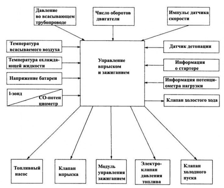
The diagram shows the input and output signals in the engine controller of a multiport injection system. Just one erroneous sensor or sensor signal or its failure can completely disrupt «equilibrium» output signals for fuel injection and ignition control. The consequence of this is a drop in engine power.
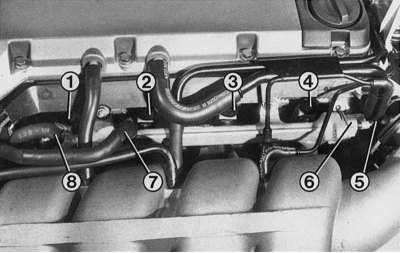
The figure shows the fuel distributor mounted parallel to the cylinder head of the 16-valve Renault 19. Injectors integrated in the cylinder head (1st to 4th), are supplied with fuel from the distribution pipeline and actuated through the block connector by the control device. Fuel line pressure (8) adjusted by controlled pressure regulator (6), located at the other end of the distribution pipeline. For this low pressure hose (5) connected to a pressure regulator. Excess fuel drain pipe (7) located in front of the fuel supply pipeline on the fuel distribution pipeline.
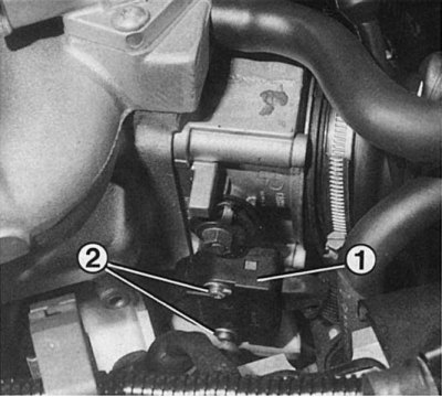
Throttle Potentiometer (1) should only be removed if necessary. To do this, disconnect the connector and then unscrew the varnished cross-head screws (2). Be sure to mark the exact position of the potentiometer before doing this.
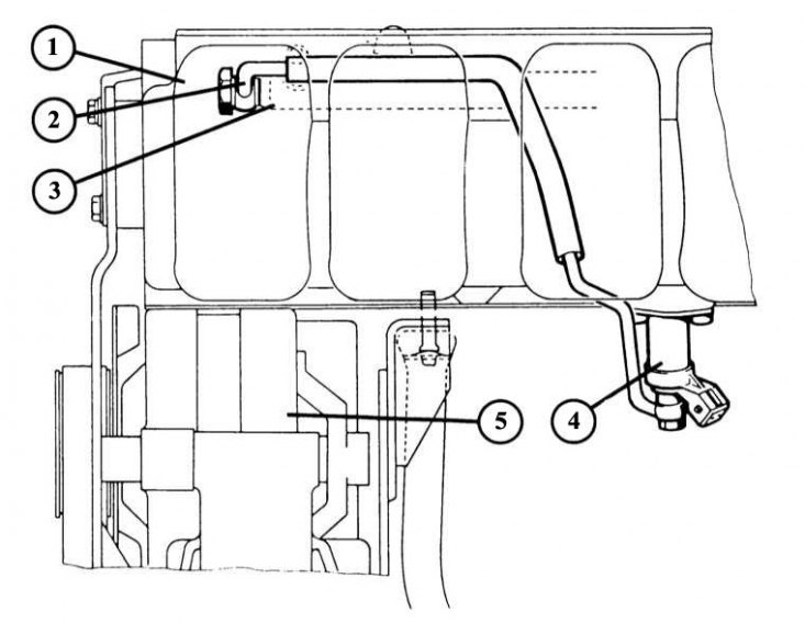
The figure shows the air distribution piping of a 16-valve engine. During operation of a cold engine, installed in the air distribution pipe housing (1) starting fuel valve (4) supplied with fuel through a high pressure fuel line (2) from the fuel distribution pipeline (3). Numeric «5» generator is marked.
Separate fuel supply
The most powerful Renault 19 models are equipped with a multipoint injection system (MPI = Multi-Point-lnjection). This means that each cylinder has its own fuel injector. The manufacturers of the main elements of the system, as in the case of a single-point injection system, remain Bendix, Bosch, Pierburg and Siemens.
The most important elements of a multipoint injection system
Fuel injection and ignition are optimally tuned, as with a single-point injection system, since the amount of fuel and the ignition timing are controlled by the control device. To do this, the control device processes information from the following elements:
- Starter terminal 1 (white wire) from start to engine start.
- The speed sensor is located on the flywheel of the crankshaft of the engine and serves to determine the position of the TDC of cylinder No. 1.
- The throttle potentiometer is located on the Bosch throttle body and serves to detect the throttle position.
- Pressure sensor for detecting underpressure in the intake manifold.
- The speed sensor is used to determine the speed of movement at the moment.
- The knock sensor is installed in the engine housing to determine «detonation» combustion, see chapter Ignition system.
- The lambda probe is located in the catalyst inlet pipe to determine the residual oxygen content in the exhaust gas.
- The intake air temperature sensor is located in the intake air hose in front of the throttle body (1.7-/1.8-liter engine) and respectively on the side of the intake manifold (16 valve engine) serves to determine the intake air temperature.
- The coolant temperature sensor is installed in order to register the temperature of the engine.
- Based on the information about the speed, speed and pressure in the intake pipe, the control device calculates the opening time of the electromagnetic injectors and thus regulates the amount of fuel injected. To this end, the control unit has at its disposal various characteristics of the state of the engine for injection and ignition. Universal data is a compact information block of all possible engine conditions with their respective injection quantities and ignition timings. The control device can also vary the values when corrective signals are received (e.g. intake air and coolant temperature).
Throttle body
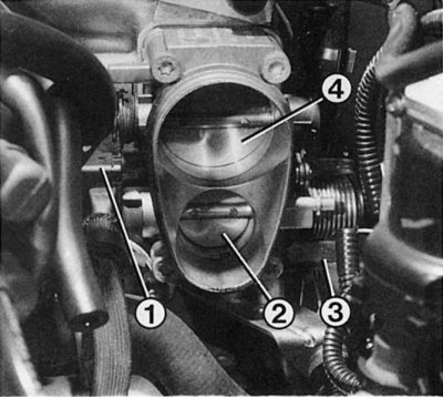
Throttle shaft lever (3), potentiometer (1) and primary throttle (2) located on the throttle shaft. Only when the maximum fuel delivery position is reached, the secondary throttle (4) fully opens the intake port in the throttle body through the lever segment. To avoid sticking when closing the primary throttle, it remains slightly ajar when the gas pedal is released. This damper position is set at the factory and cannot be changed during service. Therefore, the corresponding adjusting screw is sealed.
In the throttle body, which is located in front of the intake manifold, there are 2 throttle valves with different diameters (1.7 liter engine = 32/36mm; 1.8-liter engine = 32/36; 16-valve = 35/52 mm). The small throttle is connected via a shaft lever and a cable to the gas pedal. It regulates the intake air flow up to the middle of the gas pedal stroke. Although the large throttle only begins to open when the small throttle is nearly open, both valves simultaneously fully open the intake port in the throttle body when the maximum fuel position is reached.
Throttle Potentiometer
Throttle valve potentiometer registers the position of the throttle valve, starting from the position «idle move» (throttle closed) and before «full load» (both throttle valves are fully open). Based on this data, idle speed control, engine braking cut-off or full throttle enrichment are activated. In addition, a fast opening of the throttle valves is recognized as an acceleration signal and the acceleration rich mode is activated.
Pressure regulator
This regulator is located directly in the fuel distributor and regulates the fuel pressure to the injectors, depending on the engine variant, in the range of 3.0±0.15 bar or, respectively, from 3.5±0.2 bar. For this, a reduced pressure in the intake pipe is transferred to it. At idle with closed throttles and reduced pressure, it maintains a pressure of 0.5 bar less.
When the pressure rises and the engine load is higher, the fuel pressure is increased by the pressure regulator. The excess fuel injected in this case is discharged through the fuel line back in the tank.
Pressure meter
It is connected by a hose to the suction pipe. In the sensor, a certain reduced pressure in the suction pipe acts on the crystal chip and changes its resistance. By changing the resistance and speed, the control device determines the optimal load on the engine.
Nozzles
Directly in front of the intake valve of each of the cylinders are nozzles. To them, for one revolution of the crankshaft, half of the required amount of fuel is simultaneously injected. Thus, each cylinder receives the amount of fuel it needs in 2 «injection», the first half being injected into the intake air with the intake valve closed.
On the next rotation of the crankshaft, the second half of the required amount of fuel is injected into the intake air with the intake valve open.
Fuel distributor
It provides a uniform supply of fuel to the injectors. In addition, the distribution pipe acts as a fuel accumulator and thus prevents pressure fluctuations.
Starting fuel valve16-valve
This solenoid valve at a coolant temperature of less than 20°C injects additional finely atomized fuel into the intake manifold for a short period of time. The duration of the injection is determined by the control device.
Idle air control valve
During warm-up with a fully turned steering wheel with an amplifier or when a high power consumer is turned on, the valve opens an additional air channel; at the same time, the throttle valves are closed. More air supplied to the intake manifold causes a simultaneous increase in fuel delivery. Thus, the load from friction in a cold engine and the load on the engine from a servomotor or other powerful current consumer are compensated.
Movement speed sensor
This sensor in the electrical connection of the tachometer shaft of the gearbox generates an alternating current, the frequency of which increases or decreases depending on the speed of the tachometer shaft. Its signals are also sent to the control device.
Lambda probe
It is installed in the exhaust pipe before the catalytic converter and is electrically heated to reach operating temperature as quickly as possible after a cold start. You will find the necessary information about the design of the lambda probe in chapter «Exhaust gas neutralization».
Temperature sensor
The sensor works as a variable resistance with «negative temperature coefficient» (NTC). This means that the resistance will decrease with increasing temperature.
Intake air temperature sensor: it is located in the air hose in front of the throttle body (engines with a volume of 1.7-/1.8 l) and, accordingly, near the suction pipe in front of the intake manifold (16 valve engine) for recording the intake air temperature.
coolant sensor (located next to the thermostat housing): When starting a cold engine and during warm-up, it transmits data on the temperature of the coolant necessary for correct fuel metering and correction of the ignition timing.
This is how a multi-point injection system works
Starting a cold engine: In addition to the intake air, the idle air control valve allows additional air to enter.
At the same time, the control device receives a signal «engine cold» from the coolant temperature sensor. Based on this signal, the control device ensures that the nozzle openings are opened for a longer time to create a richer working mixture. The fuel start valve is also briefly activated by the control unit (16 valve engine only) to supply additional fuel.
Warm up: about the increasing heating of the coolant, the sensor transmits a signal to the control device. It causes the idle air control valve to close and corrects the injection timing.
Idling: from throttle potentiometer and pressure sensor signals control unit «learns», when the engine is idling. If the idle speed drops, the idle air control valve opens its vent port, which increases the amount of fuel injected.
Normal operation mode: does not require any special devices. The position of the throttle valves, the pressure of the suction pipe and the signal from the speed sensor determine the duration of the opening of the nozzle openings. The correct, most favorable fuel-to-air ratio for combustion is automatically set.
Acceleration: about the quick opening of the throttle valves, the control device «learns» via throttle potentiometer signal and «perceives» its like acceleration. In this regard, the injection time is slightly increased.
Lambda regulation: For flawless operation, the catalyst needs a constant change in the degree of enrichment of the working mixture. The value of the residual oxygen content in the exhaust is transmitted by the lambda probe to the control device, which sends a command for the duration of the injection, and at the same time the required amount of fuel is supplied.
Full load: To develop maximum power when the gas pedal is fully depressed, the engine needs more fuel than usual. By means of a signal «full throttle opening» from the throttle valve potentiometer in combination with the corresponding suction pipe pressure control device «learns» state «full load» and leaves the injectors open for injection for a longer time, while the signal from the lambda probe is ignored.
RPM limit: to protect the engine from exceeding the maximum allowable engine speed, the control device turns off the injectors if the speed sensor registers a speed of 7000 rpm.