
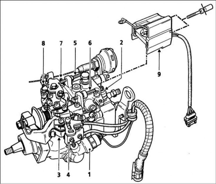
1 - Solenoid valve control depending on the load (ALFB); 2 - Winding of the fuel cut-off valve; 3 - Microswitch for preheating/exhaust gas recirculation valve; 4 - Air conditioner microswitch; 5 - Screw for adjusting the speed of deceleration; 6 - Screw for adjusting the maximum speed; 7 - Idle adjustment screw; 8 - Fast idle adjustment screw; 9 - Electronic block of the coded valve
Lucas High Pressure Fuel Pump Components
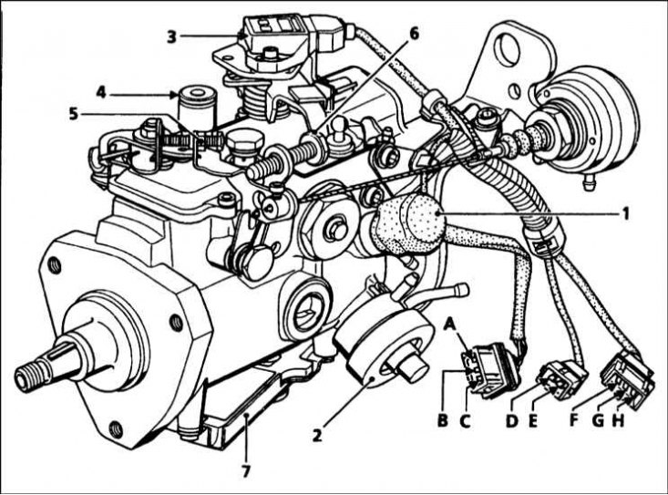
1 - Injection advance corrector; 2 - Boost pressure corrector; 3 - Throttle lever potentiometer; 4 - Plug of the control hole of the moment of injection; 5 - Idle adjustment screw; 6 - Screw for adjusting the speed of deceleration; 7 - Electronic block of the coded valve; A - Mass; B - + After turning on the ignition; C - Coded line; D - Injection advance corrector control; E - + after turning on the ignition; F - Mass; G - Signal of the gas control lever; H - Power supply 5V to the throttle lever potentiometer
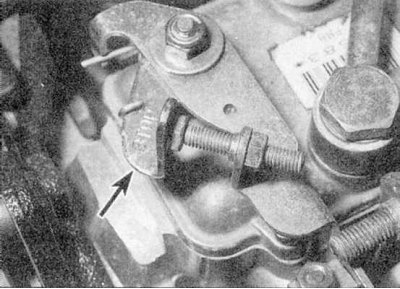
Lever arm (arrow) manual fuel cut-off - high pressure fuel pump LUCAS
Models with F8Q engine
The fuel system consists of a fuel tank, a fuel filter with a water separator, a high pressure fuel pump, injectors and related components. When passing through the filter, the fuel is heated by a special element that is installed in the filter housing. The F8Q 784 and 786 engines have a turbocharger. The exhaust system is of a conventional type, but some models may be equipped with an exhaust gas recirculation system and / or an uncontrolled catalytic converter, which reduce the amount of harmful impurities in the exhaust gas.
Fuel is pumped from the fuel tank by a high pressure fuel pump.
Before reaching the pump, the fuel passes through the fuel filter, where it is cleaned of foreign objects and water. Excess fuel lubricates the rotating pump components and then returns to the tank (refer to illustrations).
The high pressure fuel pump is driven by a toothed belt and rotates at half the speed of the crankshaft.
The F8Q 620 engine has a Bosch fuel pump. The high pressure required to introduce fuel into the compressed air in the combustion chamber is achieved by a cam plate acting on a separate piston. The fuel passes through a central rotor with one outlet, which is alternately aligned with the outlet channels of the injectors.
The fuel dosage is controlled by a centrifugal regulator, which reacts to the position of the gas pedal and engine speed. The regulator is connected to a metering valve that increases or decreases the amount of fuel injected for each pump stroke.
The main injection moment is set by the manufacturers when the pump is installed. With the engine running, the injection timing is automatically matched to the crankshaft speed by a special mechanism that rotates the cam plate or ring.
The solenoid valve on the pump is used to temporarily correct the injection timing during a cold start.
The solenoid valve is controlled by the preheat control unit or by a height sensor. When the coolant temperature is less than 29°C, when the engine is started, the valve winding is energized. If the coolant temperature sensor is defective, then the further operation of the valve will depend on the air temperature, which is measured by a temperature sensor installed on the control unit. If both sensors are faulty, the solenoid valve will automatically turn on for 200 seconds each time the engine is started. It is also energized through a relay controlled by the altitude sensor when the ambient pressure reaches 900±20 mbar.
The F8Q 784, 786 and 788 engines are fitted with a Lucas DPC fuel pump.
This pump consists of an injection advance corrector controlled by an electronic unit. The fuel in the pump passes into the hydraulic head through a metering valve connected to the gas pedal cable and the boost pressure corrector. The hydraulic head consists of two pistons pointing in opposite directions, held together by rollers moving in a ring. The moment of injection is determined by the signal coming from the needle lift sensor of the 1st injector.
A separate device is also designed to increase the fuel supply with increasing boost pressure.
Four fuel injectors inject fuel into swirl chambers in the cylinder head. The injectors are calibrated in such a way that they open and close only at certain pressures, ensuring efficient ignition of the air-fuel mixture. The injector needle is lubricated by fuel that accumulates in the spring chamber and is directed to the fuel pump return hose through the outlet tube.
Starting from a cold state is assisted by a heater or spark plugs "glow", installed in each vortex chamber (Chapter Engine electrical equipment).
The fast idle system is controlled by a thermal actuator or a vacuum actuator, depending on the model.
On models with thermal fast idle (F8Q engines), a temperature sensor in the cooling system controls the fast idle lever on the fuel pump via a cable to increase the idle speed until the engine is warm.
On models with vacuum drive (F8Q 784, 786 and 788 engines), the fast idle cable is controlled by a vacuum drive through an electromagnetic unit. The solenoid unit is controlled by the preheat control unit, and on air-conditioned models there is additional control from the compressor clutch relay.
The shut-off valve cuts off fuel supply to the fuel pump rotor when the ignition is off.
Subject to the conscientious fulfillment of the specified in Specifications maintenance, the fuel injection system will last a long time. The fuel pump can outlive the engine. The main potential cause of fuel pump and injector damage is dirt or water in the fuel.
Maintenance of the fuel pump and injectors for the motorist is limited and the performance of any work not described in this Chapter must be entrusted to a Renault workshop or a specialist in fuel injection systems.
Note. Due to the lack of technical data at the time of writing this manual, the following Sections are only partially applicable to the F8Q 788 engines. Therefore, contact a Renault workshop for more information.
Models with F9Q engine
The design and operation of the injection system used on the F9Q engine is basically the same as that of the F8Q engine described above. The main difference between the two systems is in terms of injection control. On the F9Q engine, fuel metering and injection timing are controlled by an electronic injection system control unit (ECU). This system is similar in operation to the engine management system found on gasoline models and uses similar sensors to provide an electronic control module with the data needed for various engine operating conditions. Sensors monitor coolant temperature, air temperature, fuel flow, engine speed, vehicle speed, atmospheric pressure, fuel temperature, and gas pedal position. Based on this data, the ECU controls the fuel pump, calculating the amount of fuel injected and injection timing, the preheat system, the exhaust gas recirculation system, the anti-theft engine immobilizer and engine shutdown.
Subject to the conscientious fulfillment of the specified in Specifications maintenance, the fuel injection system will last a long time. The fuel pump can outlive the engine. The main potential cause of fuel pump and injector damage is dirt or water in the fuel.
Maintenance of the fuel pump and injectors for the motorist is limited and the performance of any work not described in this Chapter must be entrusted to a Renault workshop or a specialist in fuel injection systems.
If a malfunction occurs in the injection system, first check that all system wiring is securely connected and not oxidized. Also check that the air filter element is clean, the engine compression is good and the engine breather hoses are not clogged or damaged.
If the problem persists after these checks, contact a Renault workshop, which has the ability to check the system using the Renault XR25 diagnostic tester. The tester will quickly and easily identify the problem, eliminating the need to test all system components individually, which is time consuming and can damage the ECU.
Warning! When working on fuel system components, especially fuel injectors, some precautions must be taken. See the warnings at the beginning of Sections.