
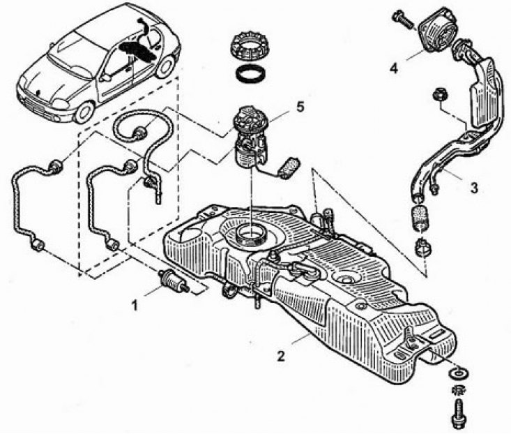
Fuel system. 1 - Fuel filter, 2 - Fuel tank, 3 - Fuel filler pipe, 4 - Fuel filler trim, 5 - Fuel pump assembly.
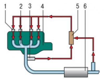
Air-fuel ratio control circuit diagram: 1 - nozzle; 2 - exhaust manifold; 3 - control sensor for oxygen concentration in exhaust gases (Lambda probe); 4 - engine; 5 - electronic engine control unit; 6 - catalytic converter of exhaust gases
The fuel system includes a fuel tank located at the rear of the vehicle, an electric fuel pump built into the tank (submerged in fuel), fuel filter and piping system. The system also includes an electronic control unit (ECU), various sensors, components and wiring of the fuel injection system.
The fuel pump delivers fuel under pressure to the fuel rail, which serves as a reservoir for the injectors installed on each cylinder, which inject fuel into the intake tracts.
The engine is equipped with a Siemens-Sirius fuel injection system. This is a distributed injection that supplies fuel in accordance with the order of operation of the cylinders at the start of the intake stroke.
To obtain information about which of the cylinders is currently in the intake stroke, the ECU uses a single TDC and engine speed sensor, which determines:
- TDC pistons of the first and fourth cylinders;
- TDC pistons of the second and third cylinders.
The system includes two oxygen concentration sensors in the exhaust gases, one of which is installed before the catalytic converter, and the second after it. The signals from the sensors inform the ECU about the deviation from the normal process of combustion of the mixture in the cylinders and serve to correct this process in order to optimize engine performance.
The coolant temperature sensor informs the ECU about the thermal state of the engine.
Air enters the system through an intake silencer attached to the air filter. The engine intake air temperature sensor tells the ECU about the temperature of the air passing through the throttle valve.
The crankshaft position sensor informs the ECU about the engine speed and the position of the pistons in the cylinders.
The knock sensor informs the ECU about a deviation in the combustion process, accompanied by detonation in the cylinders. The change in engine load is transmitted to the ECU by a pressure sensor installed in the intake manifold.
The ECU controls the engine idle speed via the idle speed controller (stepper motor), which is mounted on the throttle body. The regulator directs the opening of the bypass air channel, bypassing the throttle valve. If the throttle is closed (fuel pedal released), the ECU instructs the regulator to control the intake of air into the engine, thus adjusting the idle speed.
A potentiometer mounted on the accelerator pedal informs the ECU about the position of the throttle valve at any given moment of engine operation.
To correct the idle speed when an additional load is switched on (air conditioner, power steering pump) a sensor is used by which the computer increases the idle speed, thereby preventing the engine from stopping.
To improve the environmental friendliness of the engine and increase its efficiency, a trapping system is used (adsorption) fuel vapors with their subsequent afterburning in the engine cylinders. The recirculation valve of this system is also controlled by the ECU.
Upon receipt of information from the sensors about an emergency situation, the ECU is reconfigured to the backup engine control mode. In this case, the ECU ignores abnormal signals and, using the remaining signals, issues commands to continue engine operation, albeit with a decrease in fuel efficiency and dynamics. At the same time, a warning signal lights up on the instrument panel and the corresponding fault code is entered into the memory of the computer.
The system has a built-in inertial fuel cut-off sensor that is triggered upon impact in the event of a traffic accident. The sensor stops the fuel pump from flowing out if the fuel lines are damaged.
The ignition system works in conjunction with the fuel injection system according to the ECU commands.
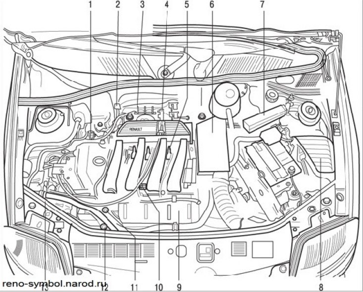
Figure 3.93. The location of the elements of the fuel injection system in the engine compartment: 1 - pressure sensor; 2 - stepping motor of the idle speed controller; 3 - throttle position sensor; 4 – upper oxygen concentration sensor; 5 - coils and spark plugs; 6 - coolant temperature sensor and top dead center sensor; 7 - ECU of the injection system; 8 - power relay; 9 - knock sensor; 10 – air temperature sensor; 11 - fuel distribution rail and fuel pressure regulator; 12 – the pressure switch of the amplifier of a steering; 13 - adsorber with solenoid valve
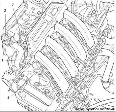
Figure 3.94. Location on the engine of the injection system elements: 1 - pressure sensor; 2 - stepping motor of the idle speed controller; 3 - throttle position sensor; 4 - ignition coil
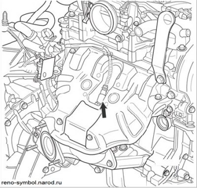
Figure 3.95. Upper Oxygen Sensor
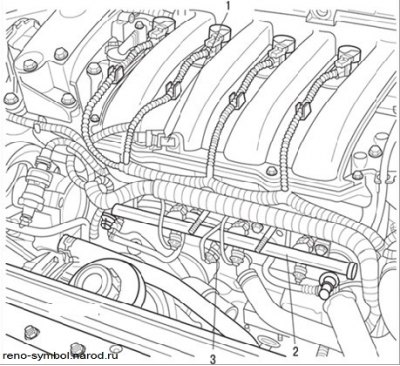
Figure 3.96. Location on the engine of the sensor (1) intake air temperature, rail (2),knock sensor (3)
The location of the elements of the fuel injection system is shown in Figures 3.93, 3.94, 3.95, 3.96.
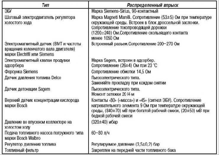
The technical characteristics of the injection system are given in Table. 3.7.
Table 3.7. Technical characteristics of the injection system
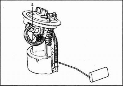
Fuel pressure control
Fuel pressure control (4) installed in the tank at the fuel pump/fuel level sensor assembly.
Fuel pressure check
Special tool:
- Pressure gauge with hose and seals - Mot. 1311-01
- Adapter - Mot. 1311-08
Examination
1. Remove the fuel manifold protection.
2. Remove the bolt (1) fastening of the fuel supply hose.
3. Install the adapter in place of the hose (tee) Mot. 1311-08.
4. Connect a pressure gauge Mot. 1311-01 and fuel supply hose (1).
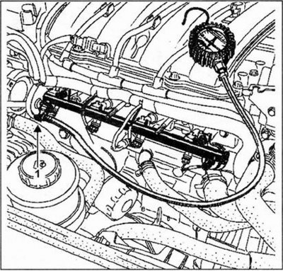
5. Start the engine.
6. After the fuel pressure has stabilized, read the pressure gauge.
Fuel pressure:
- For a circuit with a return - 3.5±0.06 bar
- For a circuit without return - 3.5 bar
Collision Fuel Cutoff
To reduce the risk of fire in the event of a collision, a fuel cut-off system is installed on the vehicle. Restoration of fuel supply after repair is carried out mechanically by cocking the inertial switch (1). A switch is installed in the fuel pump circuit between terminal 1 of the fuel pump relay and "a plus" power source.
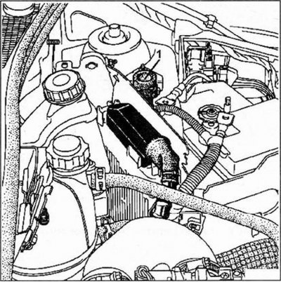
In the event of a collision, the inertial mass of the circuit breaker (steel ball) due to its movement, it breaks the power supply circuit of the fuel pump. The power supply is turned off at the fuel pump and injectors. To restore the power circuit after repair, you need to press the inertial switch button. After that, be sure to reset the fault code (fuel pump power cut) from the memory of the control unit.