
Note. the Siemens injection system is described below "Sirius 32" for the K7J 700 engine, the K4J engine uses a similar system with some design differences.
General information
Table. The main components of the Siemens injection system "Sirius 32" for K7J 700 engine.
| Name | Brand/Type | Characteristics |
| Control block | SIEMENS "SIRIUS" | 90 pin connector |
| Type of injection system | - | Multi-point injection |
| stepper electric motor | PHILIPS | Resistance:» 53 ohm at 25°C |
| Throttle Potentiometer | PIERBURG | Included in the throttle body Conductor resistance: 1200±240 ohm Moving contact resistance: < 1050 ohm |
| Magnetic sensor (TDC and engine speed) | ELECTRIFIL or SIEMENS | Resistance: 200 - 270 Ohm |
| Canister solenoid valve | SAGEM | Integrated in adsorber Resistance: 26±4 ohm at 23°C |
| Nozzle | SIEMENS | Resistance: 14.5 ohm at 20°C Leak rate: 0.7 cm3in a minute (maximum) |
| Pressure meter | DELCO ELECTRONICS | Resistance: -100 kOhm |
| Knock sensor | SAGEM | Piezoelectric type (tightening torque 20 Nm) |
| Oxygen sensor | NTK | Contacts 80 (weight) and 45 (signal) Heater resistance: 6±1 Ω at 23°C Rich: > 750±70 mV Lean: < 150±50 mV |
| Refrigerant pressure sensor | TEXAS INSTRUMENTS | The air conditioning control unit is integrated into the injection system control unit |
| Ignition coil | SAGEM | Coil monobloc type with four outputs |
| Candles | EYQUEM | RFC50LZ2E, Tightening torque: 25 - 30 Nm |
| Manifold pressure at idle | - | 330±40 mbar |
| Submersible fuel pump | - | 3±0.06 bar per 80 l/h for circuit with return 3.5 bar: 160 l/h for circuit without return |
Replacing the electronic control unit for the injection system
Electronic control units are supplied without codes, but ready for programming. When replacing the unit, you must enter the car code into it, and then make sure that the immobilizer system is working. To do this, just turn on the ignition for a few seconds, and then turn it off. The immobilizer system is activated when the key is removed.
Features of checks of the electronic control unit of the injection system
Attention! Remove the key from the ignition lock. After 10 seconds, the immobilizer system indicator should start flashing. Vehicles of this model are equipped with a special type of control unit, which must be coded in order for it to work. Therefore, it is recommended not to test electronic injection control units taken from a warehouse or from another vehicle in order to avoid coding and decoding problems. which can lead to the failure of these control units.
Inspection Equipment
It is recommended to use a universal digital multimeter for testing. It must have a high input impedance (not less than 10 kOhm/V) and measurement ranges: for voltage 0-20 V. for resistance 0-200 Ohm and 0-20 kOhm. In some cases it is necessary to use an oscilloscope.
Verification procedure
- Make sure the ignition is off.
- Connect test probes with contacts that match the lead sizes to the meter.
- For easier access to the connector, remove the control unit.
- To access the connector pins from the wire side, remove the connector cover or protective cover.
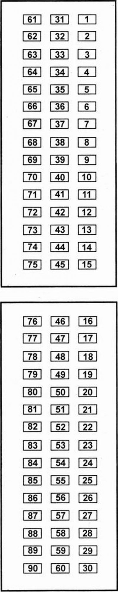
- Check the connection of the control unit connector. - According to the connector diagram, determine the numbering of the pins.
- Meter probes should only be connected to the leads on the wire side. One probe is connected to the output of the connector, and the other to ground or another output of the control unit.
Attention. Avoid short circuiting leads to ground. This can lead to failure of the control unit, wiring or sensors. Pay attention to the terms of the test (For example: "ignition ON". "cranking by starter" or "speed 3000 rpm"). Measure the signals at the specified pins and compare with the nominal signal value or waveform shown in the table.
Electronic control unit for injection system
Assignment of input-output contacts of the electronic control unit of the injection system.
 | 1 - switch (cylinders 2 and 3)
3 - mass of the power circuit 4 - solenoid valve of the fuel vapor recovery system 8 - relay 1 of the electric fan unit of the coolant temperature control system 9 - indicator of engine overheating 10 - air conditioning compressor 12 - idle speed regulator (contact B) 13 - coolant temperature sensor 15 - mass of the pressure sensor 16 - manifold pressure sensor 18 - refrigerant pressure sensor 19 - knock sensor screen 20 - knock sensor 24 - crankshaft speed sensor 26 - diagnostics 28 - mass of the power circuit 29 - "+" after the ignition switch 30 - "+" to the ignition switch 32 - switch (cylinders 1 and 4) 33 - mass of the power circuit 38 - relay 2 of the electric fan unit of the coolant temperature control system 39 - drive relay 41 idle speed controller (contact A) 42 - idle speed controller (contact C) 43 - throttle potentiometer 45 - oxygen sensor 46 - air conditioning 49 - air temperature sensor 53 - vehicle speed sensor 54 - crankshaft speed sensor 56 - diagnostics 58 - immobilizer 59 - nozzle 1 60 - nozzle 3 63 - heated oxygen sensor 66 - "+" after the ignition switch 68 - fuel pump relay 70 - information about the engine speed 72 - idle speed controller (contact D) 73 - mass of the coolant temperature sensor 74 - power throttle potentiometer 75 - throttle potentiometer ground 77 - mass of the air temperature sensor 78 - pressure sensor supply 79 - mass of the knock sensor 80 - mass of the oxygen sensor 82 - mass of the refrigerant pressure sensor 83 - refrigerant pressure sensor power supply 85 - pressure sensor in the power steering system 89 - nozzle 4 90 - nozzle 2 - input signal, - output signal |
Diagnosis of the SIEMENS injection system "SIRIUS 32" (using the K4J engine as an example)
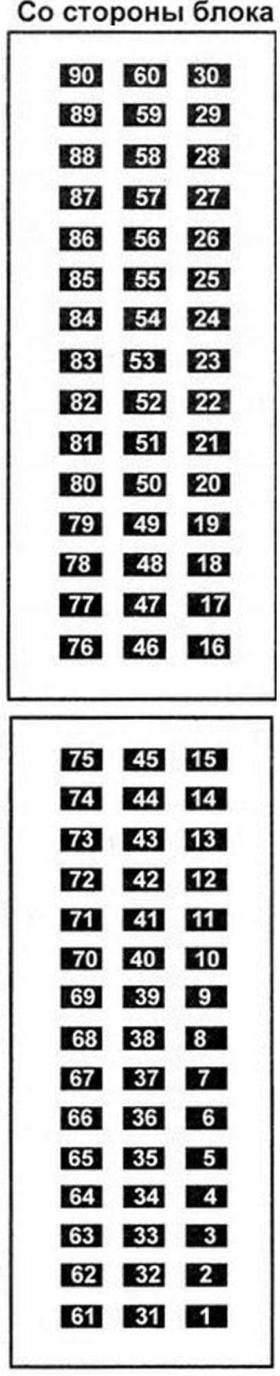
Conclusions of the connector of the electronic control unit
 | 1 - ignition coil control 2-3,
3 - mass of the power circuit, 4 - absorber cleaning control, 8 - control of relay 1 of the electric fan unit of the coolant temperature control system, 9 - coolant temperature lamp, 10 - air conditioning compressor control, 12 - idle speed controller control (contact B), 13 - input of the coolant temperature sensor, 15 - mass of the pressure sensor, 16 - signal input of the manifold pressure sensor, 18 - refrigerant pressure sensor signal, 19 - knock sensor screen, 20 - knock sensor signal input, 24 - crankshaft speed sensor signal input, 26 - diagnostics, 28 - mass of the power circuit, 29 - "+" after the ignition switch 30 - "+" to the ignition switch 32 - ignition coil control 1-4, 33 - mass of the power circuit, 38 - control of relay 2 of the electric fan unit of the coolant temperature control system, 39 - drive relay control, 41 - idle speed controller control (contact), 42 - idle speed controller control (contact C), 43 - throttle potentiometer signal, 45 - oxygen sensor signal input, 46 - air conditioning signal, 49 - air temperature sensor input, 53 - vehicle speed input, 54 - crankshaft speed sensor signal input, 56 - diagnostics, 58 - anti-theft engine start blocking system, 59 - nozzle control 1, 60 - nozzle control 3, 63 - oxygen sensor heating control 66 - "+" after the ignition switch 68 - fuel pump relay control, 70 - information about the TDC engine speed, 72 - idle speed controller control (contact D), 73 - mass of the coolant temperature sensor, 74 - throttle potentiometer power supply, 75 - throttle potentiometer ground, 77 - mass of the air temperature sensor, 78 - pressure sensor power supply, 79 - mass of the knock sensor, 80 - mass of the oxygen sensor, 82 - mass of the refrigerant pressure sensor, 83 - power supply for the refrigerant pressure sensor, 85 - power steering pressure switch information (depends on the model), 89 - nozzle control 4, 90 - nozzle control 2 |
Inspection Equipment
It is recommended to use a universal digital multimeter for testing. It must have a high input impedance (not less than 10 kOhm/V) and measurement ranges: voltage 0-20 V, resistance 0-200 Ohm and 0-20 kOhm. In some cases it is necessary to use an oscilloscope.
Verification procedure
- Make sure the ignition is off.
- Connect test probes with contacts that match the lead sizes to the meter.
- For easier access to the connector, remove the control unit.
- To access the connector pins from the wire side, remove the connector cover or protective cover.
- Check the connection of the control unit connector.
- Determine the pin numbering according to the connector diagram.
- Meter probes should only be connected to the leads on the wire side. One probe is connected to the output of the connector, and the other to ground or another output of the control unit.
Attention! Avoid short circuiting leads to ground. This can lead to failure of the control unit, wiring or sensors.
- Pay attention to the terms of the test (For example: "ignition ON", "cranking by starter" or "speed 3000 rpm").
- Measure the signals at the specified pins and compare with the nominal signal value or waveform shown in the table.
| Components/circuits | Block Output | Signal | Conditions for the verification | Rated value | Oscilloscope settings* | Waveform |
| A/C Compressor Magnetic Clutch Relay - Some Models | 10 | Ignition ON | 11-14V | |||
| 10 | Engine running A/C OFF. | 11-14 V | ||||
| 10 | Engine running air conditioning ON. | 0.1V | ||||
| Electronic air conditioning control unit some models | 10 | Ignition ON | 11-14V | |||
| 10 | Engine running A/C OFF. | 11-14V | ||||
| 10 | Engine running air conditioning ON. | 0.1V | ||||
| 23 | ¦ | |||||
| 46 | Engine running air conditioning ON. | 0 B | ||||
| Air conditioning refrigerant pressure sensor - some models | 18 | Ignition ON | 0.6 V | |||
| 82 | Ignition ON | 0 B | ||||
| 83 | Ignition ON | 5 V | ||||
| Air conditioning - windshield defroster signal - some models | 88 | ¦ | ||||
| Accumulator battery | 30 | Ignition OFF | 11-14V | |||
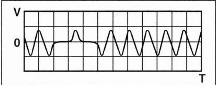
| crankshaft position sensor | 24 | Ignition ON | 1.9 V | |||
| 24 | Idling | 0.9 V? | 1V/1ms | 1 | ||
| 54 | Ignition ON | 1.9 V | ||||
| 54 | Idling | 0.9 V? | 1V/1ms | 1 | ||
| Diagnostic connector | 26 | Ignition ON | 0 B | |||
| 56 | Ignition ON | 0 B | ||||
| Weight | 3 | Ignition ON | 0 B | |||
| 28 | Ignition ON | 0 B | ||||
| 33 | Ignition ON | 0 B |
| Components/circuits | Block Output | Signal | Conditions for the verification | Rated value | Oscilloscope settings* | Waveform |
| Engine management relay | 39 | Ignition OFF | 0 B | |||
| 39 | Ignition ON | 0.1V | ||||
| 66 | Ignition ON | 11-14V | ||||
| Cooling Fan Motor Relay | 8 | Ignition ON | 11-14V | |||
| 8 | Motor running Condenser fan motor OFF. | 11-14 V | ||||
| 8 | Engine running Condenser fan motor ON. | 0 B | ||||
| 38 | Ignition ON | 11-14V | ||||
| 38 | Engine running Cooling fan motor OFF. | 11-14V | ||||
| 38 | Engine running Cooling fan motor ON. | 0.1V | ||||
| High coolant temperature indicator | 9 | Ignition ON - the indicator is off | 11-14V | |||
| 9 | Engine running indicator off | 11-14V | ||||
| 9 | Engine running indicator light on | 0 B | ||||
| coolant temperature sensor | 13 | Ignition ON coolant temperature 10°C approx | 3.5 V | |||
| 13 | Ignition ON coolant temperature 90°C approx | 0.5V | ||||
| 73 | Ignition ON | 0 B | ||||
| Solenoid valve for fuel vapor accumulator | 4 | Idling | 1% | |||
| 4 | Ignition ON | 11-14V | ||||
| Fuel pump relay | 68 | Ignition OFF | 0 B | |||
| 68 | Ignition ON | briefly 0.9 V, then 11-14 V | ||||
| 68 | engine running | 0.9V | ||||
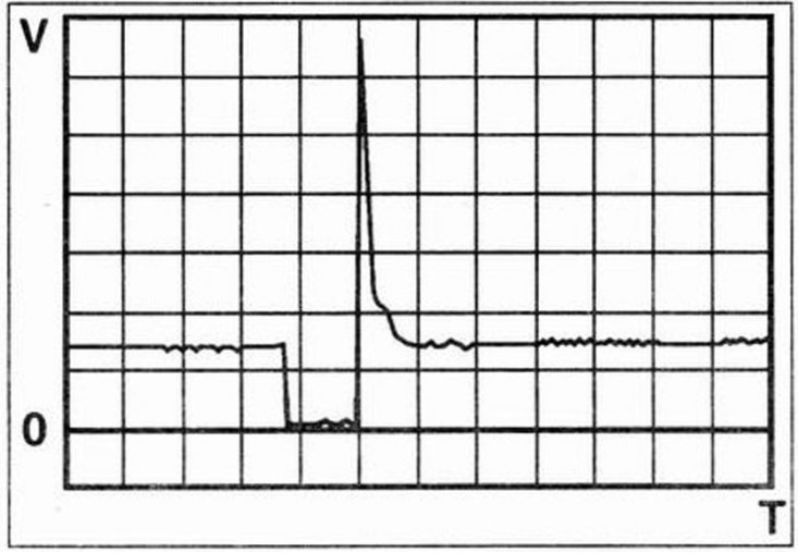
| Heated oxygen sensor - front | 45 | Ignition ON | 0.4 V | |||
| 45 | Idling | 0.1-0.9V | ||||
| 45 | Idling | 0.2V/1s | 2 | |||
| 63 | Ignition ON | 11-14V | ||||
| 63 | Idling | 5V/2ms | 9 | |||
| 80 | Ignition ON | 0 B | ||||
| Heated oxygen sensor - rear | 44 | Ignition ON | 0.4V | |||
| 44 | Idling | 0.6 V | ||||
| 65 | Ignition ON | 11-14V | ||||
| 65 | Idling | 5V/2ms | 9 | |||
| 76 | Ignition ON | 0 B |
| Components/circuits | Block Output | Signal | Conditions for the verification | Rated value | Oscilloscope settings* | Waveform |
| E / m valve control bypass air idling | 41 (72) | Idling | 4V/20ms | 4 | ||
| 12 (42) | Idling | 4V/20ms | 4 | |||
| 12 | Ignition ON | 11-14V | ||||
| 42 (12) | Idling | 4V/20ms | 4 | |||
| 72 (41) | Idling | 4V/20ms | 4 | |||
| 41 | Ignition ON | 11-14V | ||||
| 42 | Ignition ON | 0.3 V | ||||
| 72 | Ignition ON | 0.27V | ||||
| Ignition coil cylinder 1 &4 | 32 | Ignition ON | briefly 11-14 V. then 0 V | |||
| 32 | engine running | 4V/3ms | 5 | |||
| Ignition coil cylinder 2 &3 | 1 | Ignition ON | briefly 11-14 V, then 0 V | |||
| 1 | engine running | 4V/3ms | 5 | |||
| Egnition lock | 29 | Ignition ON | 11-14V | |||
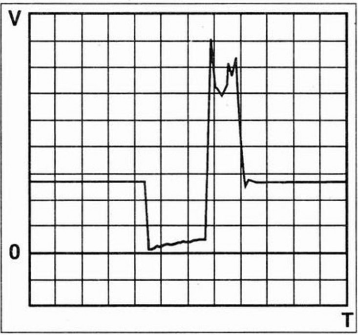
| Electronic immobilizer control unit - some models | 58 | Ignition ON | 2V/50ms | 8 | ||
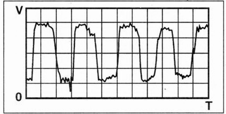
| Nozzle 1 | 59 | Ignition ON | 11-14V | |||
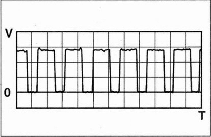
| 59 | Idling | 3.1ms | 10V/2ms | 6 | ||
| Nozzle 2 | 90 | Ignition ON | 11-14V | |||
| 90 | Idling | 3.1ms | 10V/2ms | 6 | ||
| Nozzle 3 | 60 | Ignition ON | 11-14V | |||
| 60 | Idling | 3.1ms | 10V/2ms | 6 | ||
| Nozzle 4 | 89 | Ignition ON | 11-14V | |||
| 89 | Idling | 3.1ms | 10V/2ms | 6 | ||
| Instrument cluster control unit crankshaft speed signal | 70 | Idling | 25 Hz approx | |||
| 70 | 3000 rpm | 100 Hz approx | ||||
| Instrument cluster control unit - fuel consumption signal - some models | 11 | Idling | 4V/0.2s | 3 | ||
| Instrument cluster control unit - vehicle speed signal some models | 53 | ¦ | ||||
| Intake air temperature sensor | 49 | Ignition ON air temperature 10°C approx | 2.4 V | |||
| 77 | Ignition ON | 0 B | ||||
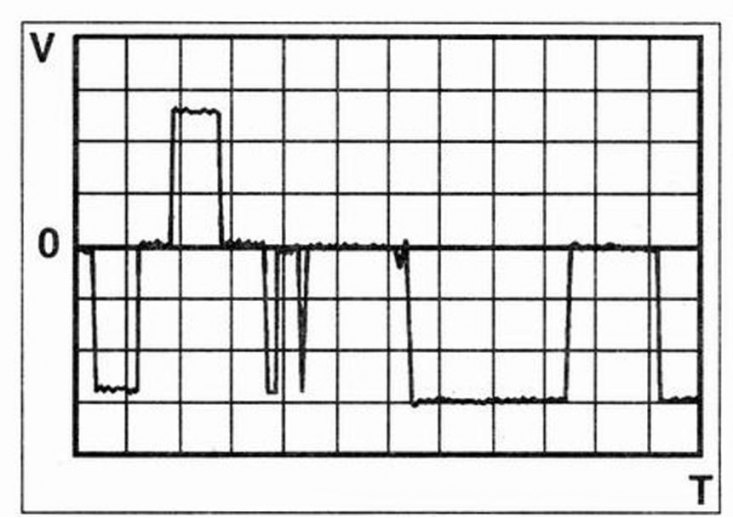
| Knock sensor | 20 | Idling - short-term acceleration | 0.1V/0.5ms | 7 | ||
| 79 | Ignition ON | 0V | ||||
| knock sensor shielded wire | 19 | Ignition ON | 0V | |||
| Intake manifold absolute pressure sensor | 15 | Ignition ON | 0 B | |||
| 16 | Ignition ON | 4.8 V | ||||
| 16 | Idling | 1.6 V | ||||
| 16 | Idling - short-term acceleration | 4.8V | ||||
| 78 | Ignition ON | 5 V |
| Components/circuits | Block Output | Signal | Conditions for the verification | Rated value | Oscilloscope settings1 | Waveform |
| Fault indicator (MIL) - some models | 34 | Ignition ON - indicator is on | 0 B | |||
| 34 | Engine running indicator off | 1-14V | ||||
| Multifunctional control unit some models | 58 | Ignition ON | 2V/50ms | 8 | ||
| Multifunctional control unit some models | 88 | ¦ | ||||
| 58 | ¦ | |||||
| Power steering pressure switch - some models | 85 | Engine running steering wheel stationary | 11-14V | |||
| 85 | Engine is running Steering wheel is turning | 0 B | ||||
| Throttle position sensor | 43 | Ignition ON throttle closed | 0.5 V | |||
| 43 | Ignition ON throttle valve fully open | 4.5 V | ||||
| 74 | Ignition ON | 5 V | ||||
| 75 | Ignition ON | 0 B | ||||
| Electronic control unit automatic transmission | 27 | ¦ | ||||
| 57 | ¦ |
* - Approximate settings - price divisions voltage/time.
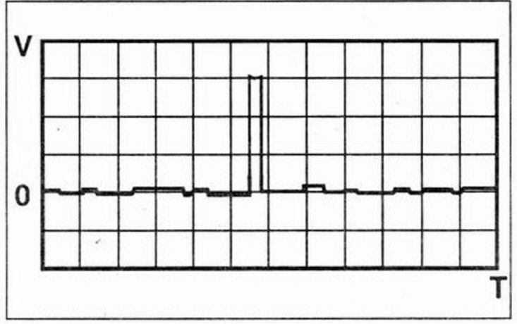
Waveform
1 - Analogue, alternating current, frequency modulated.
2 - Analog, direct current.
3 - Digital, direct current, pulse modulated or digital, direct current, frequency modulated.
4 - Digital, direct current, pulse modulated or digital, direct current, frequency modulated.
5 - Digital, direct current, frequency modulated.
6 - Digital, direct current, pulse modulated.
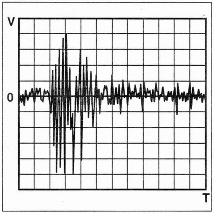
7 - Analog, AC.
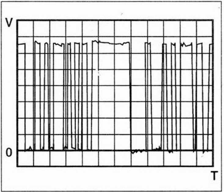
8 - Digital, direct current.
9 - Digital, direct current.