
Attention! The upper and lower sensors have different characteristics and are not interchangeable.
Removal and installation of the top gauge of concentration of oxygen in the fulfilled gases
Removing
- disconnect the wire from the negative terminal of the battery;
- remove the air filter housing;
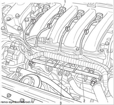
Figure 3.96. Location on the engine of the sensor (1) intake air temperature, rail (2),knock sensor (3)
- Disconnect the sensor connector and remove the sensor using tool Mot. 195 (see Figure 3.96).
Installing the sensor is carried out in the reverse order of removal.
Note. Make sure the heat shield is securely attached between the oxygen sensor and the manifold (to avoid overheating, which can lead to the destruction of the sensor connector).
Removal and installation of the knock sensor
The knock sensor is installed in the rear wall of the cylinder block (see Figure 3.105). The process of removing and installing the sensor is described in subsection «Ignition system».
Removal and installation of the temperature sensor of incoming air
The location of the sensor on the motor is shown in Figure 3.97.
Removing the sensor is not difficult. Separate a contact socket and turn out the gauge. Install the sensor in the reverse order of removal.
Removal and installation of the sensor of temperature of a cooling liquid
The sensor is installed in the thermostat housing. It is a resistor with a negative temperature coefficient of resistance, i.e. as the air temperature rises, the electrical resistance of the sensor decreases (see table. 3.6). The verification and installation process is described in the subsection «Cooling system».
Removing, installing and checking the throttle potentiometer
Removing
- remove the throttle body as described above;
- Loosen the mounting screws and remove the potentiometer from the throttle body.
Installation
- correctly align the potentiometer with the throttle axis;
- screw in the potentiometer mounting bolts;
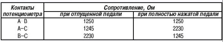
- check the resistance between the contacts of the potentiometer, which must correspond to those given in table. 3.8 values.
Table 3.8. Resistance between potentiometer contacts depending on the position of the accelerator pedal
Removal and installation of the crankshaft position sensor
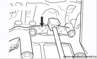
Figure 3.107. crankshaft position sensor (arrow)
The crankshaft position sensor is located on top of the clutch housing on the left side of the engine block (Figure 3.107).
Removing
- remove the air filter housing;
- disconnect the connector from the sensor;
- unscrew the mounting bolts and remove the sensor.
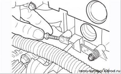
Figure 3.108. Special bolts used to mount the crankshaft position sensor
Installation is carried out in the reverse order of removal, while paying attention to the shaped mounting bolts (Figure 3.108), which cannot be replaced by others, as the gap between the sensor and the flywheel teeth may be broken.