
Attention! When working with fuel system components, observe fire safety measures.
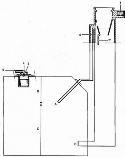
Fuel tank diagram. 1 - Fuel tank vent valve, 2 - Restriction valve, 3 - Overfill and tip-over valve, 4 - Overflow valve ball, 5 - Tank vent valve when refueling, 6 - Fuel vapor recovery system connection, A - Ventilation hose tank when refueling, B - Free volume for expansion, C - Filler neck with check valve, D - Useful volume of refueling.
Description
1. Fuel tank ventilation valve. When blocking the lines for removing fuel vapors from the tank to the fuel vapor recovery system, the valve relieves excess pressure when the engine is off or eliminates the vacuum in the tank when the engine is running. This prevents deformation of the tank.
2. Limit valve. This valve prevents filling the tank with leaded gasoline or diesel fuel.
3. Valve overflow and cut-off fuel when capsizing. Overfilling of the tank is prevented by closing off the pressure relief line with the valve ball. Filling the tank goes like this. so that there is free volume in it for the thermal expansion of the fuel. In the event of a rollover, the ball closes the pressure relief line and prevents fuel from escaping through the fuel vapor accumulator.
4. The fuel tank has a sealed filler cap.
5. The filler neck of the unleaded gasoline tank has the following features: - Smaller filler neck that cannot be fitted with a gun used to dispense leaded gasoline.
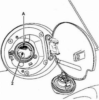
Valve (2). sealing the filler neck (prevention of fuel ejection during refueling).
Fuel drain
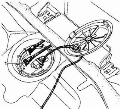
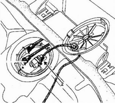
1. Remove the access cover to the fuel pump/fuel level sensor assembly.
2. Disconnect the fuel hose quick connector (Green colour).
3. Connect a process hose of sufficient length to the fitting of the removed hose and lead it into a container for collecting fuel.
4. Connect a charger to the battery to prevent it from discharging.
5. Remove the fuel pump relay (in the fuse box in the engine compartment).
6. Install a jumper on terminals 3 and 5 of the relay base to start the fuel pump.
7. After draining the fuel, remove the jumper, reinstall the fuel pump relay.
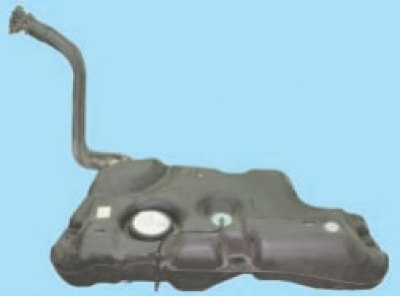
Removing the fuel tank
1. Disconnect the battery.
2. Put the car on a lift.
3. Disconnect the connector (2) and hoses of the pump/fuel level sensor assembly.
4. Raise the vehicle.
5. Disconnect the auxiliary silencer from the converter.
6. Hang the exhaust pipe on the wire.
7. Disconnect the fuel return hose from the tank.
8. Remove the heat shield from the tank and parking brake cables.
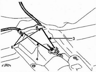
9. Loosen the parking brake lever and cables (3) And (4). Cable tension adjustment is carried out from the passenger compartment. Carefully remove the plastic stoppers (6).
10. Disconnect the overflow protection tube from the tank.
11. Disconnect the filler neck from the tank.
12. Release the parking brake cables from the clamps located under the tank.
13. Place a jack under the tank.
14. Turn away four bolts of fastening of a tank.
15. Tilt the tank to the right and up, remove the tank.
Fuel tank installation
The fuel tank has three oval holes for mounting bolts (two on the side and one on the back) to adjust the position of the tank relative to the subframe.
The tank is installed in the reverse order of removal. Do not kink or kink pipes and/or fuel system hoses. Install heat shields correctly.
- Tightening torque of the fuel tank mounting bolts - 21 Nm