
Removing
1. Unscrew bolts of fastening and remove a connecting spacer between the top support of amortization racks on mudguards.
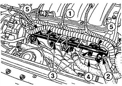
2. Disconnect the crankcase ventilation hoses 1 and 2 from the cylinder head cover (see illustration).
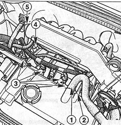
5.2 Disconnect the crankcase ventilation hoses 1 and 2 from the cylinder head cover
3. Disconnect the plug 3 of the fuel injectors power supply, as well as the plug 4 of the canister solenoid valve (see illustration 5.2).
4. Disconnect the low pressure hose 5 from the fuel pressure reducing valve (see illustration 5.2).
5. Disconnect the supply 6 and return 7 fuel hoses from the distribution fuel line (see illustration).
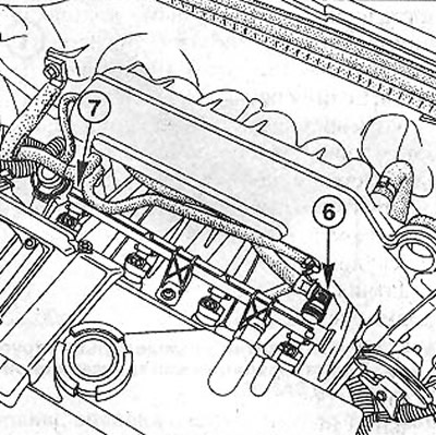
5.5 Disconnect supply 6 and return 7 fuel hoses from the distribution fuel line
6. Squeeze the sides of the hose clamp to lift the drivers A and B (see illustration). If the clamp has a tool for removing hoses RENAULT Mot. 1311-06, then insert it from the side into the clamp and push.
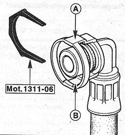
5.6 Squeeze the hose clamp from the sides to raise the drivers A and B
7. Unscrew bolts of fastening of a distributive fuel line (see arrows in illustration).
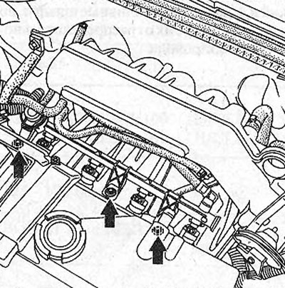
5.7 Unscrew the bolts of the distribution pipe (see arrows)
8. Remove the fuel distribution line with the connected fuel injectors by pulling it up. The fuel injectors are simply inserted into the holes and can be easily removed.
9. Remove the retaining clips 8 and disconnect the injectors from the fuel distribution line (see illustration).
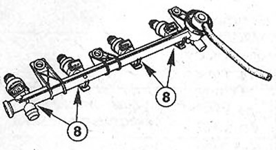
5.9 Remove the retaining clips 8 and disconnect the injectors from the fuel distribution line
Installation
10. Put the nozzles in their places and fix with locking brackets.
11. Lubricate O-rings 1 with Vaseline or SAE 90 gear oil (see illustration).
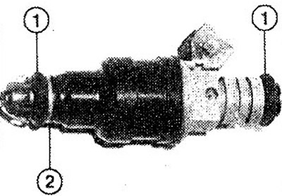
5.11 Lubricate O-rings 1 with Vaseline or SAE 90 gear oil
12. Establish a distributive fuel line together with atomizers on a head of the block of cylinders, without allowing a distortion.
Attention! When installing the injectors, make sure not to damage the O-rings 1 of the round section. Replace damaged rings with new ones. When doing this, pay attention to the position of the sealing ring 2 (see illustration 5.11). O-rings should be lubricated only with Vaseline or gear oil before installation.
13. Fix the distribution fuel line with three bolts with a tightening torque of 8 Nm.
14. Connect the supply and return fuel hoses to the distribution fuel line. The hoses should be fixed with clamps, which will be heard by a characteristic click.
15. Connect hoses 1 and 2 crankcase ventilation (see illustration 5.2).
16. Connect the power plugs for the injectors and the adsorber solenoid valve.
17. Connect the low pressure hose to the fuel pressure reducing valve.
18. Put in place the connecting spacer between the upper supports of the spring struts on the mudguards.
Vehicles with a 1.4-/1.6-liter petrol engine (K4J/K4M)
Attention! Some engines on these vehicles have a fuel rail without a return hose. In this case, the fuel pressure reducing valve is not located on the fuel distribution line, but on the fuel pump in the fuel tank.
19. Remove the cover of the distribution fuel line 1 (see illustration).
5.19 Remove the fuel distributor cap 1
20. Release from fastenings giving and returnable fuel hoses, but do not disconnect them from a distributive fuel line.
Attention! Some engines on these vehicles have a fuel rail without a return hose. In this case, the fuel pressure reducing valve 2 is also missing (see illustration 5.19).
21. Remove the low pressure hose 4 of the fuel pressure reducing valve 2 (see illustration 5.19).
Attention! Vehicles without a return hose also do not have a pressure reducing valve on the fuel distribution line.
22. Disconnect the ends of the power wires from the injectors 3 (see illustration 5.19).
23. Unscrew two bolts 5 and remove the fuel distribution line 1 together with injectors 3 (see illustration 5.19).
24. Remove locking brackets 1, acting in the direction of the arrow, as shown in the illustration.
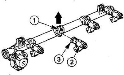
5.24 Remove retaining clips 1 in the direction of the arrow
25. Remove nozzle 2 from the fuel distribution line (eat. illustration 5.24).
26. Replace O-ring 3 before installing the nozzle (see illustration 5.24). Further installation of parts is carried out in the reverse order of removal.
27. Tighten two bolts 5 fastening the distribution fuel line (see illustration 5.19) with a force of 9 Nm.
28. Make sure the fuel hoses and power plugs are firmly seated.